Back in the original EDSAC computer, information was stored in a series of over 30 mercury delay lines all stored in a coffin-like box. These tubes would use the acoustic properties of mercury to reduce reflections. However, to prevent everyone involved with my delay line from going mad from either mercury poison or the large bill, I will be using air; a much cheaper and safer alternative, and sound.
How did the original work?
A series of pulses, representing the binary words being stored, were sent through the mercury and were sequentially received at the other end of the tube. Each pulse was converted back into binary and then sent back into the start of the tube. The amount of bits per tube was controlled by their frequency and the tube’s length. Most tubes could hold a multiple of 36 bits — the size of a long word — but th least important bit was usually lost due to a timing problem.
What am I doing?
For the Chip Hack EDSAC Challenge event (see past blogs) I and a few others are building an FPGA EDSAC and to demonstrate different features of this program, we are also building some recreations of the peripherals used. I am building a delay line that will be replacing the 72-bit accumulator. The accumulator could store enough bits so that two long words could be multiplied together without losing information. Sound travels a lot faster in mercury than in air and so I would not be able to recreate some of the faster tubes.
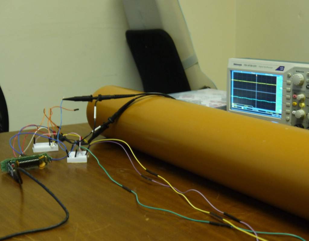
After some calculations, I found that I would have to send a pulse at 24.696kHz/m. The tube I am using is 1m long and has a diameter of 11cm. Since the microphone can only measure up to a 16kHz sine wave, I will be sending one 36-bit word every second, or one 72-bit word over 2 seconds. Due to the large diameter of the tube, there shall be a lot of reflections which could cause the word to be lost quite early on.
Attempt 1

I first built a ring oscillator out of NOR gates whose inputs were linked together for the clock. This circuit had a large noise problem at 12 kHz and so I went on to use an Arduino instead.
The software is run on an Arduino Uno and uses the TimerOne library, which masks some of the registers that control timer 1 — the 16 bit clock/ counter — to loop every 80us, 12kHz. During each loop the microphone is read and stored, and the next signal is sent to the speaker. digitalRead is used instead of analogRead, since digital read takes fewer clock pulses to implement. The speaker can send a pulse every 12kHz.
On the microphones side of the circuit, there are two inverting amplifiers that create an output of over two hundred times the original microphone output. This is followed by a simple threshold circuit formed by a LM339 with a potential divider on the non-inverting input, and the output from the amplifiers on the inverting input. The LM339 requires the difference between the non-inverting and inverting inputs to be over 2 volts and the chosen threshold voltage is 2.5v, since the higher bound of the signal is about 3 volts. This detection circuit lends itself to the digitalRead function; if the signal is not 0 then a pulse has been sent.
I designed and 3D printed a holder for the microphone and for the speaker. The holders were designed so that the microphone or speaker was at the center or the tube’s entrance and could be held in place by string. I also tried to make them as thin as possible but was limited by the accuracy of the 3D printer available.
Unfortunately, the speaker output contained very few signals with frequency of 12kHz or below, because the Arduino output was a square wave. The harmonics of the chosen frequency were louder than the wanted frequency and acted as noise. I also had a lot of problems with trying to get the microphone to work; the signal was too small and required an addition battery pack to amplify using common emitter circuits.
Attempt 2
Using two already made circuits from Elegoo, one for the microphone and the other for the buzzer, I was able to easily put the hardware for the next attempt together. The buzzer is an active buzzer, which means that when it is provided with a positive voltage a 4kHz signal is produced. The microphone could easily sense a 4kHz signal. This means that I could program the Arduino so that if output is a 1, the buzzer plays a sound for one clock cycle, during which the microphone can record the information.
I first used a very long clock cycle of 1 second to demonstrate that the idea could work. After a small amount of programming it worked, apart from the first bit of the sequence which was always a 1. The TimerOne library used in the past attempt could be added so as to give more control of the timings. Slowly the clock time was decreased so as to fit more then one bit in the tube at a time.
To decrease the strength of the loud, annoying sound I covered the ends of the tube with foam that could absorb some of the sound. The foam could also reflect some information, thus adding to the noise which would be bad and require some ways of encoding the information so that it can be recovered or lost less easily to be tried.
TimerOne library: [http://playground.arduino.cc/Code/Timer1]
Attempt 1 GitHub repo: [https://github.com/maryEmbecosm/delay_line]
Peripherals GitHub repo (attempt 2): [https://github.com/embecosm/edsac-peripherals]
If you have any ideas or are attending Chip Hack and would like to make your own delay line, please contact me below with any thoughts or questions you may have.