 | Services and Modeling for Embedded Software Development |
|---|
| Services and Modeling for Embedded Software Development |
|---|

Application Note 1. Issue 2
May 2010
Copyright © 2008, 2010 Embecosm Limited
 | The document entitled " Building a Loosely Timed SoC Model with OSCI TLM 2.0 " by Jeremy Bennett of Embecosm is licensed under a Creative Commons Attribution 2.0 UK: England & Wales License. See the Legal Notice for details. |
Table of Contents
Or1ksimExtSC Wrapper Module
UartSC Module Class
TermSC Module Class
Or1ksimIntrSC Module Class
The Open SystemC Initiative (OSCI) has issued the second version of its standard for Transaction Level Modeling (TLM) in June 2008 [6]. This defines an interface for writing high level software models of hardware. An updated version (TLM 2.0.1) was released in July 2009.
The OSCI standard is comprehensive. As well as a powerful general purpose interface, it defines a number of convenience components to facilitate adoption of the technology.
This application note provides an introductory tutorial on using TLM 2.0 for loosely timed models—ideally suited for early development of embedded software. It demonstrates through a practical case study the development of a complete SoC, capable of running a modern Linux 2.6 kernel, using the TLM 2.0 convenience components.
One of the most important components in any SoC system model is the processor core Instruction Set Simulator (ISS). This application note demonstrates how to wrap an existing ISS to provide a TLM 2.0 compliant interface.
This application note is the first in a series from Embecosm (www.embecosm.com), providing case studies in OSCI TLM 2.0 use. The objective is to provide an introduction to TLM 2.0 within a practical context. Examples are provided throughout, based on open source components, which are freely reusable under the GNU General Public License.
Issue 2 of the application note is based on TLM 2.0.1. The wrapping of the ISS is extended to cover modeling of the JTAG interface and its connection to the GNU debugger, GDB.
To aid in understanding how the components fit together, this issue includes UML class and sequence diagrams, showing the relationships and interaction between classes.
The examples have been reworked to make them easier to build. In particular the example OpenRISC programs are now also built automatically.
Finally, Robert Günzel (see Section 1.4), as well as making a number of well informed suggestions for improvements which I have adopted, has written a paper on using this application note under Mac OS (Appendix B).
SystemC represents a challenge to engineers, because it bridges the divide between the worlds of hardware and software. These are two distinct disciplines, the languages of hardware design such as Verilog and VHDL are very different in philosophy to the languages of software development such as C++ and Java. Yet both are brought together in the world of the System on Chip SoC, where large embedded software systems must run on complex silicon chips often containing multiple processor cores of different architectures.
This application note is aimed at any engineer intending to bridge the gap between hardware and software. It recognizes that the reader will most likely be expert in only one of these. Explanation is provided throughout of both the hardware ideas and software ideas being covered.
The reader is assumed to have basic programming familiarity with C and C++ and the key concepts of object oriented programming: classes and instances of classes. A basic understanding of system level hardware design and the construction of SoC from components linked by buses (or on-chip networks).
Familiarity with SystemC is assumed. The user guide supplied with SystemC provides a good introduction [7].
The OSCI TLM 2.0 standard represents a significant advance in standardizing the creation of fast models of hardware.
However the OSCI reference implementation lacks training material and examples to introduce new users to the technology.
This series of Embecosm Application Notes was prompted by a customer requesting assistance in porting an existing ISS to the TLM 2.0 standard. This is the first application note in the series. Further Embecosm Application Notes, addressing different aspects of TLM 2.0 are available from the Embecosm website at www.embecosm.com.
I am indebted to Dipl Ing Robert Günzel of the Department of Integrated Circuit Design at the Technische Universität Braunschweig, Germany, who made a number of suggestions for improvements (which I have adopted) and provided the instructions for Mac OS (see Appendix B).
The development of SystemC as a standard for modeling hardware started in 1996. Version 2.0 of the proposed standard was released by the Open SystemC Initiative (OSCI) in 2002. In 2006, SystemC became IEEE standard 1666-2005 [5].
OSCI has several groups working on supplementary standards. One of these is the TLM Working Group. It proposed its first standard for transaction level modeling in 2005. Two drafts for version 2.0 were released in 2006 and 2007. The version 2.0 standard issued in June 2008, with a minor update (2.0.1) issued in June 2009 [6].
Most software languages are not particularly suited to modeling hardware systems[1]. SystemC was developed to provide features that facilitate hardware modeling, particularly the parallelism of hardware, in a mainstream programming language.
An important objective was that software engineers should be comfortable with using SystemC. Rather than invent a new language, SystemC is based on the existing C++ language. SystemC is a true super-set of C++, so any C++ program is automatically a valid SystemC program.
SystemC uses the template, macro and library features of C++ to extend the language. The key features it provides are:
A C++ class, sc_module, suitable for
defining hardware modules containing parallel
processes
![[Note]](./images/note.png) | Note |
|---|---|
Process is a general term in SystemC to describe the various ways of representing parallel flows of control. It has nothing to do with processes in the Linux or Microsoft Windows operating systems. |
A mechanism to define functions modeling the parallel
threads of control within sc_module
classes;
Two classes, sc_port and
sc_export to represent points of
connection to and from a sc_module;
A class, sc_interface to describe the
software services required by a sc_port
or provided by a sc_export;
A class, sc_prim_channel to represent the
channel connecting ports;
A set of derived classes, of
sc_prim_channel,
sc_interface,
sc_port and
sc_export to represent and connect common
channel types used in hardware design such as signals, buffers and
FIFOs; and
A comprehensive set of types to represent data in both 2-state and 4-state logic.
The full specification is 441 pages long [5]. The OSCI reference distribution includes a very useful introductory user guide and tutorial [7].
To understand transaction level modeling, it is essential to understand the difference in approach to parallelism taken in hardware and software design.
A hardware engineer, typically writing in a
Hardware Description Language (HDL)
such as Verilog or VHDL, describes a design as a collection of
parallel activities, which communicate via shared data. The parallel
activities are always (Verilog) or
process (VHDL) blocks. The shared data structures
are wires or signals.
This follows very naturally the way that physical hardware behaves. There is no one flow of control—all parallel components are active at the same time, with their individual flow of control.
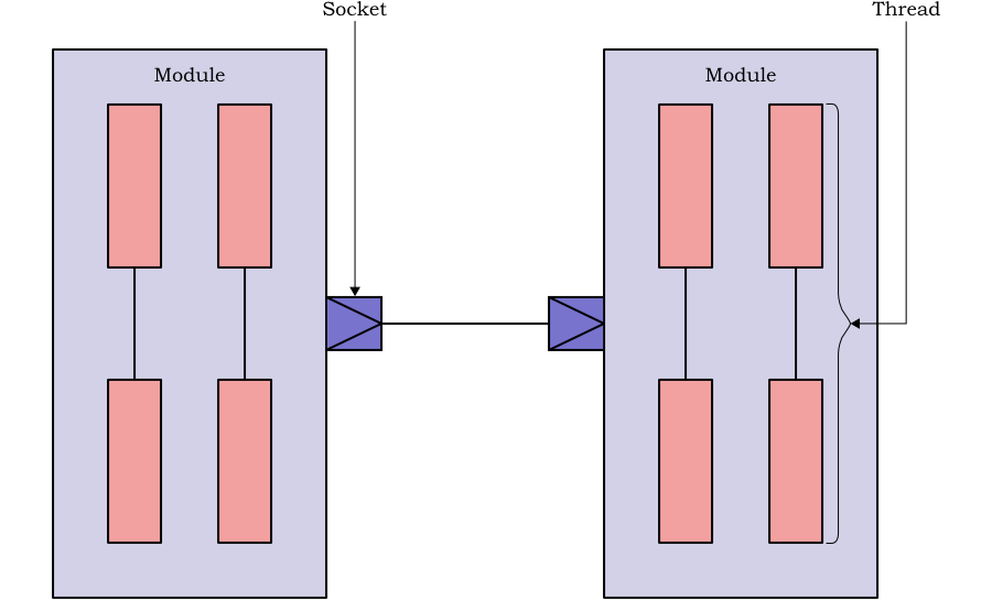
By contrast, a software engineer typically describes parallelism in a design as a number of threads, which pass flow of control between them. The threads communicate by a number of mechanisms (message passing or remote procedure call for example), but although there is logical parallelism, only one thread is ever physically active at one time.
This follows naturally the behavior on a conventional uni-processor CPU, where there is a single program counter indicating the next instruction to execute, and so only one flow of control. Even with modern multiprocessors, this is still a natural way of programming for the software engineer, because the number or threads or processes will often exceed the number of processor cores available.
A simple way to model hardware is via a round-robin, which updates the state of each component as time advances. Each component is represented as a software function. A master clock function calls each component function in turn when the clock advances—for example on each clock edge. The wires between the components are represented as variables shared between the components. A number of tools (e.g. ARC VTOC, ARM RealView SoC Designer, Carbon SpeedCompiler, Verilator) use this approach to cycle accurate modeling.
With its close parallel of the way hardware is designed with languages such as Verilog and VHDL, this approach has merit for detailed modeling. It is well suited to cycle accurate modeling where every hardware register and wire must be accurate.
Efficiency demands that not every HDL process or
always is built as a separate function. Automated
tools which generate cycle accurate models in SystemC from HDL can
often reduce complex designs to a small number of functions executed
on each cycle.
For less detailed models, the overhead in calling each component whenever time advances cannot be justified.
The solution is to model each component only when it has something to do. The individual components communicate by sending messages requesting data be transferred between each other. The exchange of messages is called a transaction, and the approach Transaction Level Modeling (TLM).
This mirrors the way hardware behaves at the high level, where functional blocks communicate by reading and writing across buses.
OSCI TLM 2.0 offers a standard approach to building Transaction Level Models.
At the simplest level a TLM is a set of SystemC modules (i.e. C++ classes), each providing one or more sockets through which the SystemC modules may read and write data.
The behavior of each module is provided by a number of parallel threads (functions of the C++ class), which communicate with the threads in other modules by passing data (i.e. reading or writing) through the sockets. This communication is known as a transaction and the data passed as a payload. Figure 2.1 shows the key components in a TLM 2.0 model.
The data passed in a transaction may take any form. However the TLM 2.0 standard defines a generic payload which is suitable for many uses, and which can be extended if required. By using the generic payload, a TLM 2.0 model will maximize interoperability.
The main features of the generic payload are:
Is this a read or a write?
What is the address (in the hardware sense of an address in memory).
A pointer to the physical data as an array of bytes
A pointer to an array indicating which bytes of the data are valid.
An indication of whether the transaction was successful, and if not the nature of the error.
Further features provide support for streaming, custom memory management and extensions to the generic payload.
A TLM 2.0 transport function is used to pass the payload to another SystemC thread and obtain a response—i.e. a transaction.
The generic payload is suitable for modeling a wide range of bus interfaces and protocols. However where additional features are required, TLM 2.0 provides an extension mechanism. The chapter on implementing a transactional JTAG debugger interface (see Chapter 11) describes the use of this extension mechanism to model the data for a bit-serial interface.
A module's threads may act as either initiators or targets. An initiator is responsible for creating a payload (see Section 2.3.1) and calling the transport function to send it. A target receives payloads from the transport function for processing and response. In the case of non-blocking interfaces (see Section 2.3.3), the target may create new transactions backwards in response to a transaction from an initiator.
Initiator calls are made through initiator sockets, target calls received through target sockets. A module may implement both target and initiator sockets, allowing its threads to both generate and receive traffic.
There are two principal types of TLM 2.0 transport function.
The blocking transport functions are called by the initiator thread, received by the target thread, which processes the request and then returns the result. Until the transaction has been processed and released the initiator thread is blocked.
The non-blocking transport functions are called by the initiator thread, received by the target thread, which immediately returns, before processing the request. Subsequently the target, having processed the request makes a transport call backwards to the initiator to return the result.
In the non-blocking case there are actually two types of transport used. The forward transport path is used by the initiator to pass the request to the target and the backward transport path used by the target to return the response. The advantage of the non-blocking transport interface is that the initiator can carry on processing, while the target is processing the request originally made.
In addition TLM 2.0 provides two more specialized types of transaction.
A debug transaction is a read that does not affect the state of the model. These are for use by debuggers, which wish to see the state of a model, without affecting that state.
TLM 2.0 recognizes that a full-blown transaction is too heavyweight for some types of access. For example an ISS accessing memory using transactions would destroy performance. TLM 2.0 provides the concept of a direct memory interface, allowing threads direct access to blocks of memory in other threads for high performance.
TLM 2.0 considers two levels of timing detail.
A loosely timed model uses transactions corresponding to a complete read or write across a bus or network in physical hardware. It provides timing at the level of the individual transaction.
An approximately timed model breaks down transactions into a number of phases corresponding much more closely to the phasing of particular hardware protocols (for example the address and data phases of an AHB read or write).
Typically loosely timed models are implemented with a blocking interface and approximately timed models with a non-blocking interface.
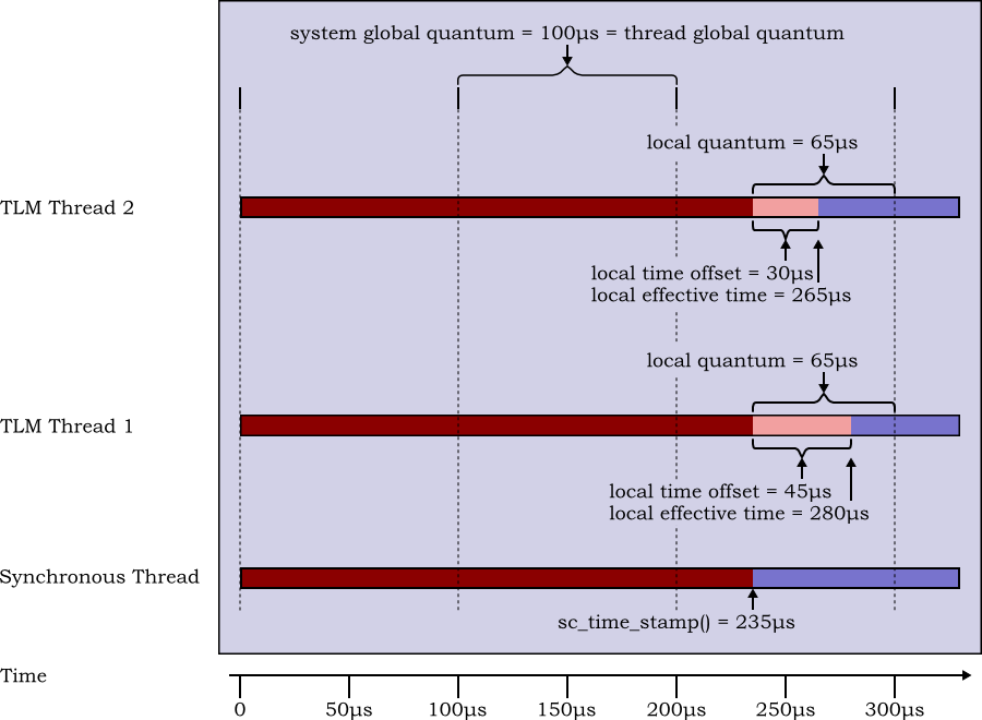
TLM 2.0 also introduces the concept of temporal decoupling. Standard SystemC keeps a single synchronized view of time, which is used by all threads in all modules. However with temporal decoupling, each thread can keep its own local view of time, allowing the thread to run ahead in simulation time, until it needs to synchronize with another thread. This improves performance in loosely timed models with blocking interfaces, by avoiding bottlenecks in processing.
To ensure that one thread doesn't run away hogging all the processing, TLM 2.0 temporal decoupling uses the concept of the quantum, the greatest amount that a thread may differ in timing from the central view of time. This allows other threads a chance to catch up
TLM 2.0 does not have an explicit concept of an untimed socket (something that was explicit in TLM 1.0). The standardization group took the view that in practice all models need some concept of time, so purely untimed models are of little value.
However, untimed models are easily implemented as loosely timed models which always set the timing parameter in transport calls to zero. The example in Chapter 4, Chapter 6 and Chapter 7 uses this approach to create an untimed model. This is then refined in Chapter 8 to add synchronous timing information and in Chapter 9 to add temporal decoupling.
The standard TLM 2.0 approach to modeling requires the user to derive their own classes from the standard TLM 2.0 sockets, so that those sockets can then implement the TLM 2.0 interfaces. Modules then instantiate these derived sockets and use the bind function to connect them to sockets on other modules.
This is a very flexible approach, but the need to define new derived classes for sockets is an unnecessary layer of complexity for simple modeling. For such uses, the TLM 2.0 standard defines a number of convenience sockets which can be instantiated directly by modules, and which specify their interface functions as callbacks.
These convenience sockets are used throughout the case study in this application note.
[1] There are some exceptions, most notably Simula67, one the languages which inspired C++. In some respects it is remarkably like SystemC.
In this case study, TLM 2.0 convenience sockets are used to wrap an existing ISS. This is then built into a simple SoC using additional hand-written TLM 2.0 components.
Modeling uses the TLM 2.0 generic payload with no extensions. It is independent of the specific bus architecture that will be used in the implementation.
The ISS used is from the OpenCores (www.opencores.org) project. This open source project has developed a complete 32/64-bit architecture, the OpenRISC 1000, complete with GNU compiler chain, architectural simulator and Linux port. This application note uses the OpenRISC 1000 architectural simulator, Or1ksim as the ISS for all the examples.
The model is constructed in a number of stages:
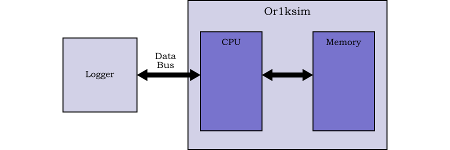
The basic wrapper for the Or1ksim ISS is built using TLM 2.0 convenience sockets and tested with a simple logger. In this first stage timing is ignored—this is effectively an untimed model. See Chapter 4 and Chapter 5.
A model UART is added as an example peripheral, demonstrating how TLM 2.0 and existing SystemC technologies can be mixed. See Chapter 6.
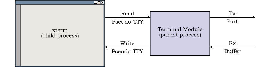
A model of a terminal is added as a test bench for the SoC. This demonstrates how to add SystemC components which use operating system I/O without blocking the SystemC thread. See Chapter 7.
Synchronous timing is added to each component, making the model loosely timed. See Chapter 8.
Temporal decoupling is added to the Or1ksim ISS, UART and terminal, to improve the performance of the model. See Chapter 9.
Interrupt modeling is added to the UART and the Or1ksim ISS, allowing the model to run Linux. See Chapter 10.
A second thread, modeling the JTAG interface to the processor is added to the wrapper. This demonstrates how the ISS wrapper can be multi-threaded, while the underlying OpenRISC 1000 ISS remains single threaded. This interface allows the model to be driven from a debugger such as GDB. See Chapter 11.
Simple applications, compiled with the OpenRISC 1000 tool chain are used throughout to exercise the model components. The final model is demonstrated booting a Linux 2.6 kernel.
The example, a simple SoC, is based on the Or1ksim ISS for the OpenRISC 1000 architecture. The OpenRISC 1000 architecture is a conventional 32-bit DSP/RISC design, with optional caches and MMU. Or1ksim is an interpreting ISS written in C, which in its standard configuration models main memory and a number of peripherals as well as the CPU itself.
A key feature of Or1ksim is that it is single threaded and the code is generally not re-entrant. Much of the challenge in wrapping such an ISS is ensuring consistency within a multi-threaded SystemC environment.
Information on obtaining and setting up the open source Or1ksim simulator and its tool chain are given in Embecosm Application Note 2. The OpenCores OpenRISC 1000 Simulator and Tool Chain: Installation Guide. [4].
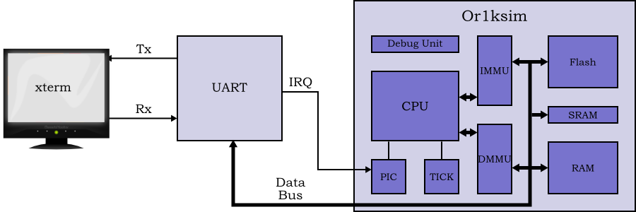
For Chapter 4 through Chapter 9 the Or1ksim ISS is configured to model only the CPU and main memory, with example peripherals modeled as separate SystemC modules. For Chapter 10, the ISS is configured to model the data and instruction MMUs and a programmable interrupt controller (PIC). This allows the ISS to support interrupt driven peripherals and hence Linux
In Chapter 11 a second thread is introduced to the wrapper to model the JTAG debugging interface. This allows the model to be run under the control of a debugger such as GDB
In Chapter 4 the TLM 2.0 wrapper for the Or1ksim ISS is developed. In Chapter 5 the wrapped ISS is tested by connection to a simple TLM 2.0 logger module. This module records transactions sent to it on standard output as shown in Figure 3.1.
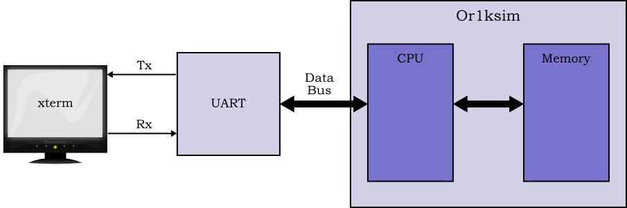
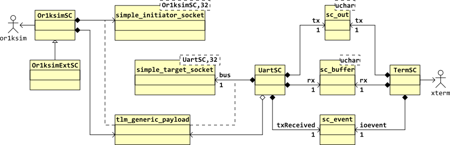
To build a simple SoC the Or1ksim ISS CPU/memory subsystem is connected to a UART modeled in SystemC using TLM 2.0. The test bench for the system is a terminal, also modeled in SystemC using TLM 2.0 as shown in Figure 3.2. The model is built up in stages starting with the ISS wrapper module developed in Chapter 4. In Chapter 6 and Chapter 7 models of the UART and terminal are added to create an untimed model. Synchronous timing to create a loosely timed model is added in Chapter 8 and temporal decoupling to improve performance is added in Chapter 9. .
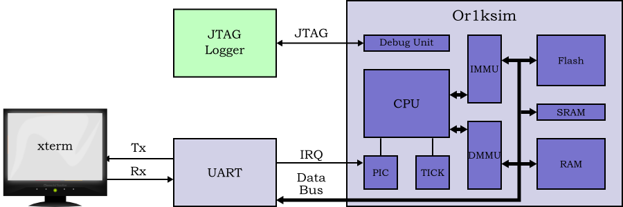
To run Linux (see Chapter 10), the example must be extended to support interrupt driver I/O. It also needs memory management and other peripheral functions. This is provided internally to the Or1ksim ISS. This design is shown in Figure 3.3.
A software debugger typically interacts with a processor via an independent debugging interface. For the OpenRISC 1000 the debug interface uses IEEE 1149.1 JTAG. To allow the debugger to connect to the model we must model this interface. This design is shown in Figure 3.4.
The code of the distribution is organized as follows.
configure
The main configuration script.
linux.cfg
An Or1ksim configuration file for use when running Linux.
progs-or32
A collection of OpenRISC 1000 programs which run on the models created. Binaries are provided as well as source, but to recompile the example programs requires the OpenRISC 1000 tool chain. See Embecosm Application Note 2. The OpenCores OpenRISC 1000 Simulator and Tool Chain: Installation Guide. [4] for more information on building the OpenRISC 1000 tool chain.
simple.cfg
An Or1ksim configuration file for use when running simple examples.
sysc-models
The SystemC code for the various models. A separate directory is provided for each model. In each case the models build on previous models using the C++ class inheritance mechanism.
logger
The simplest model, providing a base class wrapper to Or1ksim and connecting to a simple logger class, which can check the correct behavior of the bus. See Chapter 4 and Chapter 5.
simple-soc
The simplest complete SoC model, adding a UART and
terminal emulator to the Or1ksim model. The base
Or1ksim wrapper class from logger
is extended to allow other threads to execute. See Chapter 6 and Chapter 7.
sync-soc
This extends the SoC wrapper from
simple-soc to add synchronized
timing. Derived classes of the UART and terminal
emulator also add synchronized timing. See Chapter 8.
decoup-soc
Decoupled timing is added to the SoC wrapper from
sync-soc. A decoupled version of
the UART is also implemented. See Chapter 9.
intr-soc
This is a version of the SoC wrapper from
decoup-soc which adds interrupt
handling. A version of the UART which supports
interrupt based operation is also implemented. This
allows Linux to be supported. See Chapter 10.
jtag-soc
The SoC wrapper from intr-soc is
extended with an additional thread implementing a JTAG
interface. This allows code running on the model to be
debugged using a tool such as GDB. See Chapter 11.
uml
UML design information for all the models, created with BoUML is provided in this directory.
Various other files and directories are included. These form part of the standard GNU autotools infrastructure.
The code throughout is documented with
Doxygen (see www.doxygen.org). This provides
a description of the code, generated automatically from the
source. The generated HTML can be found in the
doc/html sub-directory of both the SystemC
model directory and the OpenRISC 1000 program directory.
All the examples in this application note separate the definition of
a class (i.e. what it does) in a
.h file, from the implementation
(i.e. how it does it) in a
.cpp file. Class X is
defined in file X.hX.cpp
The examples use the convention that classes and other type names
start with an Upper Case letter
(e.g. Or1ksimSC), variables and functions
start with a lower case letter (e.g. dataBus) and
defined or enumerated constants are all in UPPER CASE
(e.g. #define BAUD_RATE 9600). All SystemC
module classes end with the characters 'SC'.
C++ provides the hierarchical class mechanism, where
derived classes inherit (some) of the
functions and variables of their
base class. This feature is heavily used
within SystemC—for example all module classes are derived
classes of the SystemC base class,
sc_module.
The SystemC models in each section of this application note are built using derived classes of the models from previous sections.
Those functions and variables which other classes will use are
declared as public. For SystemC modules this
usually means the constructor and any SystemC ports or
sockets. Occasionally there are some utility functions which are
also made public (see for example
Or1ksimExt::isLittleEndian in Section 6.3)[2].
Variables and functions in classes that are not for use by other
classes, but are required in derived classes are declared as
protected (i.e. visible to derived classes).
The remaining functions and variables, which are for use only by the
current class, are declared private (visible only
to this class). This avoids any unplanned reuse by derived classes.
Some of the functions will be reimplemented in later derived
classes. Such functions are also declared virtual.
In summary public functions and variables may be
used by any other class, protected functions and
variables may be used only by this class and
any derived classes and private functions and
variables may be used only by this class. virtual
functions may be reimplemented in derived
classes.
The entire example system is now built using the GNU; autotools. This provides for flexibility in configuration and building of the system.
| Note |
|---|---|
This is a major change since issue 1 of this application note. |
Full details of how to configure and build the models are in Appendix A.
[2]
Object oriented purists prefer to expose only class functions as
the public interface, so hiding all state
implementation from external view. There is considerable merit
in this, but the common SystemC convention is to expose actual
ports or sockets, rather than accessor functions for those
objects. This application note follows this practice.
The conversion of an existing ISS to a SystemC module with TLM 2.0 sockets involves several steps.
Modify the existing ISS (in this example Or1ksim written in C) so it behaves in a manner suitable for wrapping (see Section 4.1).
Define a SystemC module for the wrapper (see Section 4.2) and provide its implementation (see Section 4.3).
Test the wrapper with a simple logger module attached to the TLM 2.0 socket and a suitable test application running as embedded code on the ISS (see Chapter 5).
The code for the Or1ksim wrapper module
(Or1ksimSC.cpp and
Or1ksimSC.h) may be found in the
sysc-models/logger directory of the distribution.
Most ISS need some modification before they can be incorporated into a TLM 2.0 framework. Like many ISS, Or1ksim is designed as a standalone program. The options are:
Given the choice, option 2 is more flexible, making the ISS widely reusable in other environments. It is the approach adopted in this application note.
It is not intended that the reader should have to understand the internal workings of Or1ksim. All the changes described in this application note form part of Or1ksim 0.4.0.
With the exception of the examples in Chapter 11, the changes described in this application note also form part of Or1ksim 0.3.0.
Details of obtaining Or1ksim are provided in Appendix A.
The Or1ksim main function first initializes
the ISS, then sits in a loop executing instructions. This
main function is replaced by a series of
functions which form the interface to the library. The interface
functions needed are:
int  or1ksim_init (const char *config_file,
                   const char *image_file,
                   void       *class_ptr,
                   int       (*upr) (void              *class_ptr,
                                     unsigned long int  addr,
                                     unsigned char      mask[],
                                     unsigned char      rdata[],
                                     int                data_len),
                   int       (*upw) (void              *class_ptr,
                                     unsigned long int  addr,
                                     unsigned char      mask[],
                                     unsigned char      wdata[],
                                     int                data_len));
or1ksim_init initializes the
simulator. For Or1ksim, configuration data is read from a
file, which is passed as the first argument,
config_file. The program image is passed as
a second argument, image_file.
Or1ksim also needs to be able to call up to the SystemC
model of which it is part—to read and write from the
peripheral address space. These are provided as the fourth
and fifth arguments, upr and
upw. More explanation of the upcall
mechanism can be found in Section 4.2.6.
Function calls between C and C++ can be awkward. The upcall
functions form part of the SystemC module object, but are
written as static functions with C linkage. To enable these
functions to invoke functions in the SystemC module, they are
passed a pointer to the module class instance to use as a
handle. This pointer forms the third argument,
class_ptr.
int or1ksim_run( double duration );
or1ksim_run runs the simulator for the
specified time in seconds.
These functions are a standard part of the Or1ksim 0.3.0 and Or1ksim 0.4.0 libraries.
The standard Or1ksim ISS incorporates the functionality of several common peripherals. The objective of this application note is to demonstrate the ISS driving external peripherals modeled in SystemC using TLM 2.0 interfaces.
Or1ksim peripherals are configured in a textual configuration
file, with a section (introduced by the keyword
section) for each device attached. This
configuration file specifies the memory mapped addresses of the
peripheral. Any reads or writes to those addresses will be directed
to the code of the peripheral within Or1ksim.
Or1ksim is extended with a new class of peripheral,
generic, which specifies an external
peripheral. The specification in the configuration file specifies
the memory mapped address range covered and whether byte, half word
or full word access are enabled. Multiple generic
sections may be defined (for different address ranges) in the
configuration file.
Code is added to Or1ksim, so that any read or write to a
generic peripheral is redirected back to the
wrapper code via the upcalls specified as arguments to
or1ksim_init (see Section 4.1.1 and Section 4.2.6).
The class definition for the Or1ksim ISS wrapper module may be
found in the file sysc_models/logger/Or1ksimSC.h.
The Or1ksim SystemC wrapper module class,
Or1ksimSC, is defined in the file
Or1ksimSC.h. It will provide a single initiator
socket, for data access, dataBus. No instruction
accesses are planned, so modeling an external instruction bus is
unnecessary.
The module includes the tlm.h header, which
defines the core TLM 2.0 interface and the required convenience
wrapper header—in this case for a simple initiator socket.
The POSIX stdint.h header is also included, since
the definitions and code will make use of the fixed width native
types defined there.
#include <stdint.h>

#include "tlm.h"
#include "tlm_utils/simple_initiator_socket.h"
#include "or1ksim.h"
| Note |
|---|---|
There is no need to include the standard
|
The module is declared as a standard SystemC module, i.e. as a
derived class of sc_core::sc_module.
class Or1ksimSC
  : public sc_core::sc_module
{
| Note |
|---|---|
SystemC provides a macro, so that a module can be defined by: SC_MODULE( Or1ksimSC ) However this is equivalent (IEEE 1666-2005 section 5.2.5) to the C++ derived class declaration
class Or1ksimSC
  : public sc_core::sc_module
{
 public:
By using
The examples provided with SystemC and TLM 2.0 all use explicit
declarations of classes derived from
|
Or1ksimSC needs a custom constructor, which
can be passed the Or1ksim ISS configuration and image files. It
will call the or1ksim_init function within the
Or1ksim library (see Section 4.1.1) to
initialize the ISS.
Or1ksimSC( sc_core::sc_module_name  name,
           const char              *configFile,
           const char              *imageFile );
The default destructor is sufficient here. The module has no tidying up to do on termination.
The only public interface is the TLM 2.0 simple initiator convenience
socket, dataBus. The TLM 2.0 convenience sockets are
templated with
the class of which any callbacks are members;
a bus width (default BUSWIDTH, 32); and
a protocol type (default the TLM 2.0 base protocol types).
For this case study, the default bus width and protocol are
appropriate and need not be specified. There is no default class for
the template, so Or1ksimSC is used. A class must be
specified, even where (as in this case for a simple blocking
initiator) no callbacks are actually required.
tlm_utils::simple_initiator_socket<Or1ksimSC> dataBus;
The module has a single thread, which executes the instructions of
the ISS. The run function implements this:
void run();
The thread is not part of the public interface, but will but will be
reused and reimplemented in derived classes later in the application
note, so it is declared protected and
virtual.
The Or1ksim ISS makes requests to read and write peripherals via
the upcalls passed as arguments to or1ksim_init
(see Section 4.1.1).
The Or1ksim ISS is implemented in C, which cannot easily call
C++ class instance functions. The solution is to declare two
static member functions which can be called
from C. The call to or1ksim_init also received
the address of the actual C++ class instance (cast to
void *). This pointer is passed back with
the upcall, so the static function can call the corresponding
instance function.
A total of 4 functions are needed, one static and one instance each for read and write. The static functions use the native C/C++ types (unsigned long int), but convert to defined fixed width types for the instance functions. The native SystemC 64-bit unsigned type is used for the address (which is always 64 bits in TLM 2.0 function calls) and the POSIX 32-bit unsigned data type is used for the byte enable mask and data.
These upcall functions are not changed throughout this application note, so are declared private.
static int  staticReadUpcall (void              *instancePtr,
                              unsigned long int  addr,
                              unsigned char      mask[],
                              unsigned char      rdata[],
                              int                dataLen);

static int  staticWriteUpcall (void              *instancePtr,
                               unsigned long int  addr,
                               unsigned char      mask[],
                               unsigned char      wdata[],
                               int                dataLen);

int         readUpcall (unsigned long int  addr,
                        unsigned char      mask[],
                        unsigned char      rdata[],
                        int                dataLen);

int         writeUpcall (unsigned long int  addr,
                         unsigned char      mask[],
                         unsigned char      wdata[],
                         int                dataLen);
![[Caution]](./images/caution.png) | Caution |
|---|---|
It might seem logical to use the SystemC limited precision types, rather than the POSIX types. However the SystemC types are not native C++ types, so will not cast as expected. |
The transport mechanism is common to both, so provided in a utility
function, doTrans. This function will be used
and re-implemented in derived classes, so is declared
protected and virtual.
When invoked, each upcall will need to populate a new payload. Since this is something local in both scope and extent to the upcall and its lifetime, the instinct is to declare it as an automatic variable within each upcall.
However the TLM 2.0 generic payload has a large underlying structure and complex initialization, so such a local declaration carries a significant performance penalty if it is constructed each time the upcall is used.
Since only one upcall is ever in use at any one time, we can declare the payload as a class instance variable. Since it is only used by the upcalls, it can be private to this class.
tlm::tlm_generic_payload trans;
| Note |
|---|---|
The performance overhead in instantiating a generic payload is not mentioned in the TLM 2.0 LRM. I am indebted to Robert Günzel for bringing the issue to my attention. |
The class implementation for Or1ksimSC may be
found found in sysc-modules/logger/Or1ksimSC.cpp
in the distribution.
All the definitions required are obtained from the definition file:
#include "Or1ksimSC.h"
The implementation of a C++ class that is a SystemC module with
SystemC threads (SC_THREAD), methods
(SC_METHOD) or clocked threads
(SC_CTHREAD) requires a number of definitions for
that class to be set up using the SC_HAS_PROCESS
macro.
SC_HAS_PROCESS( Or1ksimSC );
| Caution |
|---|---|
The
The
In cases such as this, where the constructor implementation is
separate from the definition, SystemC requires that the
|
The constructor passes the name to the constructors of its base
class (sc_module) and its simple initiator socket
(dataBus), then calls the
or1ksim_init function in the Or1ksim library
to initialize the ISS.
The member function, run is associated with the
class as a SystemC thread, using the SC_THREAD
macro. It will be called automatically by the SystemC kernel after
elaboration (i.e SystemC initialization).
Or1ksimSC::Or1ksimSC ( sc_core::sc_module_name  name,
                       const char              *configFile,
                       const char              *imageFile ) :
  sc_module( name ),
  dataIni( "data_initiator" )
{
  or1ksim_init( configFile, imageFile, this, staticReadUpcall,
                staticWriteUpcall );

  SC_THREAD( run );               // Thread to run the ISS

}       /* Or1ksimSC() */
The main thread, run, invokes the Or1ksim
ISS to run for ever (by passing a negative time argument). The ISS
will use the upcalls (see Section 4.2.6) to request
reads from and writes to the peripheral address space.
The thread is called automatically when the SystemC kernel has completed elaboration (i.e. is initialized).
void
Or1ksimSC::run()
{
  scLastUpTime   = sc_core::sc_time_stamp();
  or1kLastUpTime = or1ksim_time();

  (void)or1ksim_run( -1.0 );

}       // Or1ksimSC()
Two functions are declared as static member functions to implement the upcalls from the Or1ksim library (see Section 4.2.6 for an explanation of why these functions are static).
The static functions receive the pointer to the
Or1ksimSC instance which originally started the
Or1ksim ISS (provided as an argument to
or1ksim_init described in Section 4.3.3).
This allows each static function to call the instance function which
implements the upcall, as shown here with
staticReadUpcall:
int
Or1ksimSC::staticReadUpcall (void              *instancePtr,
                             unsigned long int  addr,
                             unsigned char      mask[],
                             unsigned char      rdata[],
                             int                dataLen)
{
  Or1ksimSC *classPtr = (Or1ksimSC *) instancePtr;
  return  classPtr->readUpcall (addr, mask, rdata, dataLen);

}       // staticReadUpcall()
The instancePtr argument allows identification of
the particular instance of the class which called
or1ksim_run and hence to which the upcall is
directed. The remaining arguments are passed to the instance method
unchanged.
| Caution |
|---|---|
It might be thought that providing a direct upcall to the C++
upcall functions of the class would be more efficient, using the C++
member reference operator ( Linkage to static functions is much simpler and usually works between C and C++. So the approach used here is more reliable. |
The upcalls from the ISS generate the transactional activity. These functions set up the payload, execute the transaction (i.e exchange the payload and result with the target) and return the result to the ISS.
The example here is coded in a very simple fashion, in the knowledge
that the requests to read are always four bytes long (the OpenRISC 1000 has
a simple 32 bit bus), possibly with some bytes masked out for byte
and half-word reads. This matches the default
BUSWIDTH of the simple initiator socket.
As noted in Section 4.2.6, the payload is declared as a class instance variable, rather than locally here for performance reasons. This has the added benefit that it will also work should we ever convert the model to using a non-blocking socket, where the lifetime of the payload would need to be longer than the lifetime of the upcall. TLM 2.0 requires that the payload, data and mask fields all remain valid for the duration of the complete transaction.
Once the payload fields are set up, the
doTrans function (which is used for both read
and write) is called to transport the payload to the target and
return the result.
The transport function requires a time to be supplied, even when timing is not being used (as in this case). This must be time variable, not a constant, since the target can update the value. A dummy variable is declared with zero time and passed to the blocking transport function of the socket with the payload.
  sc_core::sc_time  dummyDelay = sc_core::SC_ZERO_TIME;
  dataBus->b_transport( trans, dummyDelay );
This implementation is sufficient for modeling just the Or1ksim
ISS in SystemC. However at no time does the thread execute a
SystemC wait call. In the absence of any such
yield, no other thread would be able to execute. This will be remedied
in Chapter 6 when other threads are added to model
peripherals.
The test configuration was shown earlier in Figure 3.1. For this a simple logger is needed, which must implement a TLM 2.0 simple target socket.
In addition, a simple embedded application is needed to run on the Or1ksim ISS, which will make reads and writes to peripheral address space, which can be detected by the logger.
All the behavior is in the callback function—there are no SystemC
threads. This means the logger will be suitable for testing the
Or1ksimSC wrapper module, even though its thread
never yields (see Section 4.3.5).
The code for the logger module (LoggerSC.cpp and
LoggerSC.h) and the main program
(loggerMainSC.cpp may be found with the Or1ksim
wrapper code in the sysc-models/logger directory of
the distribution.
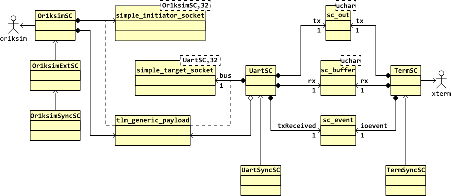
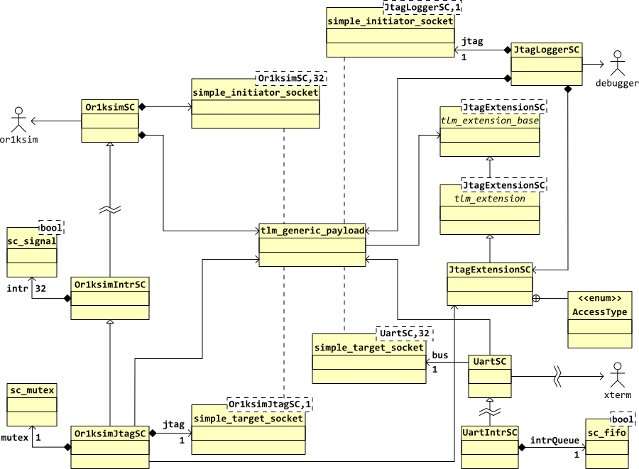
The key aspects of the overall program are captured in a UML class diagram and a UML sequence diagram, showing how a read transaction is processed.
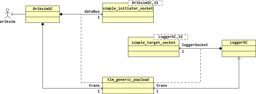
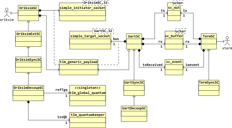
The overall class diagram for the design is shown in Figure 5.1. The Or1ksim wrapper class creates its own TLM 2.0 convenience initiator port, with which a TLM 2.0 generic payload will be associated to carry traffic. Conversely the logger class creates its own TLM 2.0 convenience target port through which it will receive the associated payload. The class structure of the underlying SystemC TLM 2.0 environment connecting initiator and target ports is not shown.
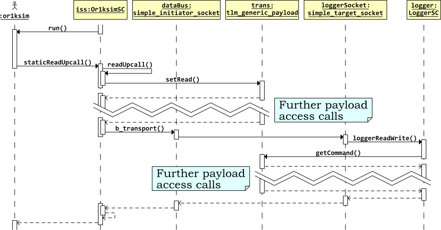
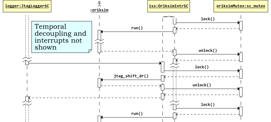
A sequence diagram, illustrating the handling of a read transaction
for the design is shown in Figure 5.2. The Or1ksim wrapper class invokes the underlying Or1ksim
ISS through its run function.
The run function executes without further
interruption. Whenever it needs to read or write via the external
bus, it uses the staticReadUpcall or
staticWriteUpcall function. This in turn
invokes the readUpcall function for the wrapper
instance.
The various TLM 2.0 generic payload functions are used to set up the
payload, before the payload is passed to the initiator port using
its b_transport function (for simplicity the
call to do_trans is omitted from the
diagram). The packet is passed internally to the connected target
port, where it invokes the handler function
(loggerReadWrite) to handle the payload. The
payload is modified as appropriate before being returned to the
initiator.
| Note |
|---|---|
All the actions in this diagram are synchronous. There is a single thread of control, which flows from the wrapper module to the logger module as a transaction is processed. |
The code for the logger module definition may be found in
sysc-models/logger/LoggerSC.h in the
distribution.
The logger is based on the TLM 2.0 convenience simple target socket, so needs the appropriate header, in addition to the standard TLM 2.0 header:
#include "tlm.h"
#include "tlm_utils/simple_target_socket.h"
The class is a standard SystemC module:
class LoggerSC
: public sc_core::sc_module
A custom constructor is needed, which will be used to register the callback function for the simple target convenience socket blocking transport.
LoggerSC( sc_core::sc_module_name name );
The public interface is the single simple target convenience socket.
tlm_utils::simple_target_socket<LoggerSC> loggerPort;
The code for the logger module implementation may be found in
sysc-models/logger/LoggerSC.cpp in the
distribution.
The logger will be doing a certain amount of stream IO, so includes the C++ headers that define stream manipulation functions. The POSIX standard integer types are also included.
#include <iostream>
#include <iomanip>
#include <stdint.h>

#include "LoggerSC.h"
The constructor passes its argument (the module) name to the base
class sc_module constructor. The body of the
function then registers the loggerReadWrite
function as the callback for blocking transport to this convenience
socket. This means that any initiator which requests blocking
transport (by calling the initiator socket's
b_transport function) will invoke this callback
function in the target.
LoggerSC::LoggerSC( sc_core::sc_module_name  name ) :
  sc_module( name )
{
  loggerPort.register_b_transport( this, &LoggerSC::loggerReadWrite );

}       // Or1ksimSC()
The callback function, loggerReadWrite records
the key information regarding any transaction it receives. The
payload is a TLM 2.0 generic payload, with appropriate access
functions. In this simple implementation, a length of 4 bytes is
assumed for the data in the payload.
To get at the data and byte enable mask, the pointers to
unsigned char are cast to pointers to the POSIX
fixed width type, uint32_t, as was used with
Or1ksimSC. Endianness issues due to the byte
pointers not being word aligned are not an issue, because the
Or1ksimSC module also declared them as
uint32_t.
void
LoggerSC::loggerReadWrite( tlm::tlm_generic_payload &payload,
                           sc_core::sc_time         &delay )
{
  // Break out the address, mask and data pointer.

  tlm::tlm_command   comm    = payload.get_command();
  sc_dt::uint64      addr    = payload.get_address();
  unsigned char     *maskPtr = payload.get_byte_enable_ptr();
  unsigned char     *dataPtr = payload.get_data_ptr();

  // Record the payload fields (data only if it's a write)

  const char *commStr;

  switch( comm ) {
  case tlm::TLM_READ_COMMAND:   commStr = "Read";   break;
  case tlm::TLM_WRITE_COMMAND:  commStr = "Write";  break;
  case tlm::TLM_IGNORE_COMMAND: commStr = "Ignore"; break;
  }

  std::cout << "Logging" << std::endl;
  std::cout << "  Command:      "   << commStr << std::endl;
  std::cout << "  Address:      0x" << std::setw( 8 ) << std::setfill( '0' )
            <<std::hex << (uint64_t)addr << std::endl;
  std::cout << "  Byte enables: 0x" << std::setw( 8 ) << std::setfill( '0' )
            <<std::hex << *((uint32_t *)maskPtr) << std::endl;

  if( tlm::TLM_WRITE_COMMAND == comm ) {
    std::cout << "  Data:         0x" << std::setw( 8 ) << std::setfill( '0' )
              <<std::hex << *((uint32_t *)dataPtr) << std::endl;
  }

  std::cout << std::endl;

  payload.set_response_status( tlm::TLM_OK_RESPONSE );  // Always OK

}       // loggerReadWrite()
The logger module and the Or1ksim wrapper module must be connected
in the main program (sc_main since this is
SystemC), and the simulation invoked.
The code for the main program may be found in
sysc-models/logger/loggerMainSC.cpp in the
distribution.
The program includes the C++ iostream header,
main TLM 2.0 header and the header of the two modules which will be
used:
#include <iostream>

#include "tlm.h"
#include "Or1ksimSC.h"
#include "LoggerSC.h"
The two iostream entities used are brought
into the local namespace.
using std::cerr;
using std::endl;
The program takes two arguments, an Or1ksim configuration file (described further in Section 5.6) and a binary image to execute on the Or1ksim ISS (see Section 5.5).
int  sc_main( int   argc,
              char *argv[] )
{
  if( argc != 3 ) {
    cerr << "Usage: TestSC <config_file> <image_file>" << endl;
    exit( 1 );
  }
Instances of the Or1ksim ISS and the logger are created, the ISS being passed the two program arguments for its initialization.
  Or1ksimSC  iss( "or1ksim", argv[1], argv[2] );
  LoggerSC   logger( "logger" );
The target socket of the logger (loggerPort) is
connected by passing it as argument to the initiator socket of the
ISS (dataBus). The C++ function application
operator, (), is overloaded for initiator sockets
to provide this binding function.
iss.dataBus( logger.loggerPort );
The test program in progs-or32/logger-test.c
defines a memory mapped volatile data structure and then writes to and
reads from each element of that structure.
The source code for the logger test program may be found in
progs-or32/logger-test.c in the distribution. It
uses the utility functions (progs-or32/utils.c
and progs-or32/utils.h) and the bootloader
(progs-or32/start.s).
The test program uses some simple utility functions which can write
characters (simputc), string
(simputs) and hexadecimal numbers
(simputh). Its header is included:
#include "utils.h"
The utilities' implementation can be found in
utils.c.
The memory mapped address is defined in the configuration of Or1ksim (see Section 5.6) to be 0x90000000. This is set as a defined constant in the test program.
#define BASEADDR 0x90000000
The memory mapped structure consists of a byte, half word (16 bits)
and full word (32 bits), all declared as volatile
within the struct. These are all declared with
the C types, which for the OpenRISC 1000 tool chain are known to correspond
to these sizes.
struct  testdev
{
  volatile unsigned char       byte;
  volatile unsigned short int  halfword;
  volatile unsigned long  int  fullword;
};
The main program declares a pointer to this
struct at the BASEADDR, along
with 3 variables to hold the results of the various sized results
when reading.
main()
{
  struct testdev *dev = (struct testdev *)BASEADDR;

  unsigned char       byteRes;
  unsigned short int  halfwordRes;
  unsigned long int   fullwordRes;
The details of each write are logged and the value then written. (In
the absence of a printf, the logging is
necessarily cumbersome).
  simputs( "Writing byte 0xa5 to address 0x" );
  simputh( (unsigned long int)(&(dev->byte)) );
  simputs( "\n" );
  dev->byte     =       0xa5;

  simputs( "Writing half word 0xbeef to address 0x" );
  simputh( (unsigned long int)(&(dev->halfword)) );
  simputs( "\n" );
  dev->halfword =     0xbeef;

  simputs( "Writing full word 0xdeadbeef to address 0x" );
  simputh( (unsigned long int)(&(dev->fullword)) );
  simputs( "\n" );
  dev->fullword = 0xdeadbeef;
The values are then read back. No results are expected (the logger does not set any values), but this should check the process behaves as expected.
  byteRes = dev->byte;
  simputs( "Read 0x" );
  simputh(  byteRes );
  simputs( " from address 0x" );
  simputh( (unsigned long int)(&(dev->byte)) );
  simputs( "\n" );

  halfwordRes = dev->halfword;
  simputs( "Read 0x" );
  simputh( halfwordRes );
  simputs( " from address 0x" );
  simputh( (unsigned long int)(&(dev->halfword)) );
  simputs( "\n" );

  fullwordRes = dev->fullword;
  simputs( "Read 0x" );
  simputh( fullwordRes );
  simputs( " from address 0x" );
  simputh( (unsigned long int)(&(dev->fullword)) );
  simputs( "\n" );
At the end of the program, the utility
simexit is used. This not only terminates the
program, but will also exit the simulation.
The program is compiled as part of the overall make and will be
found in the progs-or32 sub-directory of the
main build directory. A custom linker script ensures the program is
loaded with its bootloader at the correct address, with its entry
point at the OpenRISC 1000 reset vector (0x100).
The complete program is compiled from the top level make file. Both a
standalone program (logger) and a
libtool compliant library
(liblogger.la) are created. The library
provides a convenient mechanism for reusing the code from this
model, when creating subsequent models which use derived classes.
The SystemC modules are all compiled with
SC_INCLUDE_DYNAMIC_PROCESSES defined when
using TLM 2.0. This is a requirement for using the TLM 2.0
library. The final executable is linked against the SystemC
library.
The Or1ksim ISS is configured using a textual configuration
file, described in more detail in
Embecosm Application Note 2. The OpenCores OpenRISC 1000 Simulator and
Tool Chain: Installation Guide.
[4]. For the modified Or1ksim ISS, generic
peripherals can be added (see Section 4.1.2), which will cause code to call
out via the upcall mechanism to the Or1ksim SystemC wrapper
module (see Section 4.2.6).
The Or1ksim configuration file for this example is in
simple.cfg. It disables all the standard
peripherals and specifies one block of memory from address 0x0. It
adds a generic peripheral allowing byte, half
word and full word access to addresses mapped from 0x90000000 to
0x90000007, with the following configuration file entry
section generic
  enabled      =          1
  baseaddr     = 0x90000000
  size         =        0x8
  name         = "External UART"
  byte_enabled =          1
  hw_enabled   =          1
  word_enabled =          1
end
The compiled program can be executed by passing in as arguments the Or1ksim configuration file and the OpenRISC 1000 binary. The result is shown in Figure 5.3.
$ ./sysc-models/logger/logger ../simple.cfg progs-or32/logger-test

             SystemC 2.2.0 --- May 16 2008 10:30:46
        Copyright (c) 1996-2006 by all Contributors
                    ALL RIGHTS RESERVED

   ... <Or1ksim initialization messages>

Writing byte 0xa5 to address 0x090000000
Logging
  Command:      Write
  Address:      0x90000000
  Byte enables: 0x000000ff
  Data:         0x003f54a5

Writing half word 0xbeef to address 0x090000002
Logging
  Command:      Write
  Address:      0x90000000
  Byte enables: 0xffff0000
  Data:         0xefbe8fc4

   ... <More test program output>

Read half word 0x0FFFF from address 0x090000002
Logging
  Command:      Read
  Address:      0x90000004
  Byte enables: 0xffffffff

Read full word 0x028372F09 from address 0x090000004
exit(0)
@reset : cycles 0, insn #0
@exit  : cycles 33297, insn #16581
 diff  : cycles 33297, insn #16581
$
Figure 5.3. Output from the logger test of the Or1ksim wrapper module.
Each access from the application program generates the expected transactional access. All accesses are 32 bits wide, but for byte and half-word access the relevant bytes are masked off. The reads return meaningless values (the logger was not designed to package a return value), but in each case the value returned fits in the size requested as expected.
| Note |
|---|---|
The Or1ksim ISS can be configured to model little-endian architectures. The TLM 2.0 payloads are always packed with data using the endianness of the model. If the exercise were repeated with a little-endian version of Or1ksim the addresses of the access would be unchanged (they are word aligned), but the byte enable masks for the byte and half word accesses would be inverted. |
This example uses a single peripheral, a UART. The UART model is based on National Semiconductor 16450 design. The Or1ksim ISS wrapper must be extended to work with this UART.
The code for the UART module (UartSC.cpp and
UartSC.h) may be found with the extended Or1ksim
wrapper code (Or1ksimExtSC.cpp and
Or1ksimExtSC.h) in the
sysc-models/simple-soc directory of the
distribution.
The 16450 UART is a very long established industry component. Data written a byte at a time into the transmit buffer is converted to serial pulses on the output (Tx) pin. Serial pulses on the input (Rx) pin are recognized and converted to byte values, which can be read from the receive buffer. Typically Rx and Tx are connected to a terminal and keyboard which can generate and recognize the pulses of data. The UART can also generate additional signals for terminals and keyboards to provide physical flow control, but that is beyond the scope of this model. The key interfaces are shown in Figure 6.1.
The 16450 UART specifies a set of registers which control the UART behavior. On the Tx/Rx side, this includes setting the board rate and the pattern of stop, start and data bits. On the CPU side this includes configuring interrupt behavior (if any) and setting flags to show the status of transmit and receive buffers. The registers are shown in Table 6.1.
| Address | Register | R/W | Description |
|---|---|---|---|
| 0 |
RXBUF
| R |
When the |
TXBUF
| W |
When the | |
DLL
| R/W |
When the | |
| 1 |
IER
| R/W |
The interrupt enable register. The lower 4 bits control which events generate an interrupt. |
DLH
| R/W |
When the | |
| 2 |
IIR
| R |
Interrupt identification register. Bit 0 indicates if an interrupt is pending, bits 1-2 the reason for the interrupt. |
| 3 |
LCR
| R/W |
Line control register. Various bits controlling the behavior
of the UART. Of these, |
| 4 |
MCR
| W |
Modem control register. Bits 0-4 control the behavior of the modem. |
| 5 |
LSR
| R |
Line status register. Bits 0-6 report the status of the
UART. Of these, DR, bit 0, receiver data ready is
important, indicating there is valid data in
|
| 6 |
MSR
| R |
Modem Status Register. Bits reporting the state of the modem. |
| 7 |
SCR
| R/W |
Scratch register. Not used by the UART, but may be used by the application to store an 8-bit value. |
Table 6.1. NS 16450 UART Registers
A transaction level model cannot show all the intricacies of a UART—the whole point is to simplify and remove detail.
The TLM should allow the CPU to read and write registers and communicate with a model terminal/keyboard which will send and receive characters and generate interrupts as appropriate. While all writable registers can be written and all readable registers read, only those registers and bits of registers which are relevant to this level of modeling will have any impact on behavior.
A TLM 2.0 socket is the natural model for the bus interface to the
CPU. However the interface to the terminal is much simpler.
Standard byte wide SystemC buffers
(sc_buffer) will be suitable, one for the Rx
direction and one for Tx. The buffer is implemented for the Rx
direction and a port to a buffer for the Tx direction. The terminal
(see Chapter 7) will offer the complementary
arrangement.
| Note |
|---|---|
A SystemC buffer ( |
The interrupt is not modeled as an interface at this stage, so the UART will only be suitable for polled use. An interrupt interface is added in Chapter 10.
The divisor latch affects the baud rate, which will affect timing of transfers. This will be covered in a later section (see Chapter 8), but is not needed for the current untimed model. The value can be written and read, but does not affect behavior.
All interrupts are modeled (see Section 6.2.3), so all bits in the interrupt enable and interrupt control register are modeled.
The modem control and status registers are only modeled to the extent of supporting modem loopback. This is used by some software to determine the nature of the modem (for example in the standard Linux serial line driver).
The line control register sets details of the bit transfers. In a later section (see Chapter 8), this will affect the timing of transfers, but it is not relevant to the current untimed model.
In the Line Status Register, the Data Ready and
Transmitter Holding Empty/Transmitter
Empty bits are the only ones modeled. The model does not
distinguish a separate buffer and holding transmit register, so the
last two of these will move in step in the model.
For a larger system, the Or1ksim wrapper module described in Chapter 4 must be extended. A public function is required for peripheral models to establish the CPU endianness.
The function must be added to the underlying Or1ksim library and
then a wrapper function added to the Or1ksimSC
wrapper module.
In Section 4.3.5 it was noted that the
absence of any call to wait meant the Or1ksim
ISS could be the only thread in the model. The
doTrans function must be extended to yield
after each transaction to allow other threads to run. For our new
model, this would prevent the UART and terminal models from running.
These extensions are achieved by defining a new
class, Or1ksimExtSC derived from the existing
Or1ksimSC class. It inherits all the
functionality of the existing class, re-implements that of the transport
function, doTrans and adds an additional public
interface function, isLittleEndian.
The additional function is straightforward, since endianness is a compile time constant in the Or1ksim ISS.
int or1ksim_is_le();
or1ksim_is_le returns 1 if Or1ksim is
modeling a little endian
architecture, 0 otherwise. It is needed to ensure the payload is
packed with the correct byte ordering.
This function is a standard part of the Or1ksim 0.3.0 and Or1ksim 0.4.0 libraries.
The new class, Or1ksimExtSC is derived from
Or1ksimSC, so the definition file includes
its header. The module class can then inherit from that class.
#include "Or1ksimSC.h"

class Or1ksimExtSC
: public Or1ksimSC
{
A custom constructor must be defined. Custom constructors do not inherit, so a new custom constructor is defined just to pass the arguments on to the base class.
  Or1ksimExtSC( sc_core::sc_module_name  name,
                const char              *configFile,
                const char              *imageFile );
A new public function to report the endianness of the underlying CPU model is defined
bool isLittleEndian();
The doTrans function is reimplemented here, to
allow the thread to yield. The function remains protected and
virtual, since it will be redefined again later in this application
note.
virtual void doTrans( tlm::tlm_generic_payload &trans );
The extended Or1ksim wrapper module class,
Or1ksimExtSC, definition may be found in
sys-models/simple-soc/Or1ksimExtSC.h in the
distribution. It uses the TLM 2.0 simple target convenience socket
(described earlier in Chapter 5).
The constructor just passes its arguments to its base class
Or1ksimExtSC::Or1ksimExtSC ( sc_core::sc_module_name  name,
                             const char              *configFile,
                             const char              *imageFile ) :
  Or1ksimSC( name, configFile, imageFile )
{
 }      // Or1ksimExtSC()
isLittleEndian is a simple wrapper for the
underlying Or1ksim ISS library function[3].
bool
Or1ksimExtSC::isLittleEndian()
{
  return (1 == or1ksim_is_le());

}	// or1ksimIsLe()
The majority of the code for doTrans is
unchanged from its implementation in
Or1ksimSC. The addition is a
wait for zero time immediately after the
transaction has completed. This allows the SystemC thread to
yield, so that any other threads that are ready can take a turn.
wait( sc_core::SC_ZERO_TIME );
| Caution |
|---|---|
The call to The implementation currently is untimed, so a zero delay wait is perfectly acceptable. That just gives all the other untimed threads a turn at execution.
The logger described in Chapter 5
worked without this call to |
The extended Or1ksim wrapper module class,
Or1ksimExtSC implementation may be found in
sys-models/simple-soc/Or1ksimExtSC.cpp in the
distribution.
[3]
A technicality is that the Or1ksim library function,
is_little_endian returns an
int, since C does not have a
bool type. A C++ compiler would automatically
convert one to the other, but making the comparison explicit is
good for clarity. The same code will be generated, so there is
no loss of performance.
The UART module class, UartSC definition may
be found in sys-models/simple-soc/UartSC.h in the
distribution. It uses the TLM 2.0 simple target convenience socket
(described earlier in Chapter 5).
The header files for TLM 2.0 and the simple target convenience socket are included.
#include "tlm.h"
#include "tlm_utils/simple_target_socket.h"
Convenience constants for the address mask, named register offsets and bit fields are then defined. The address mask is needed, since in this simple SoC model there is no arbiter/decoder to strip out the higher order bits from the address before the transaction is sent to the UART.
#define UART_ADDR_MASK 7 // Mask for addresses (3 bit bus)
Named constants are defined giving the address offset of each register of the UART
#define UART_BUF  0               // R/W: Rx/Tx buffer, DLAB=0
#define UART_IER  1             // R/W: Interrupt Enable Register, DLAB=0
#define UART_IIR  2             // R: Interrupt ID Register
#define UART_LCR  3             // R/W: Line Control Register
#define UART_MCR  4             // W: Modem Control Register
#define UART_LSR  5             // R: Line Status Register
#define UART_MSR  6             // R: Modem Status Register
#define UART_SCR  7             // R/W: Scratch Register
Bit masks are declared for each of the bits and bit fields of interest in the UART. For example the interrupt identification register needs a mask for the pending bit of a mask for the two bits representing the highest priority interrupt and a mask for each possible interrupt.
#define UART_IIR_IPEND  0x01    // Interrupt pending (active low)

#define UART_IIR_MASK   0x06    // the IIR status bits
#define UART_IIR_RLS    0x06    // Receiver line status
#define UART_IIR_RDA    0x04    // Receiver data available
#define UART_IIR_THRE   0x02    // Transmitter holding reg empty
#define UART_IIR_MOD    0x00    // Modem status
The main class is a standard SystemC module class derived from
sc_core::sc_module.
class UartSC
: public sc_core::sc_module
{
The module has a customized constructor, specifying an input clock rate (which in the SoC example will be the SoC clock rate), and a flag to indicate the endianness of the model.
  UartSC( sc_core::sc_module_name  name,
          unsigned long int        _clockRate,
          bool                     _isLittleEndian );
The interfaces to the UART model are:
The simple target convenience socket, bus,
representing the bus from the CPU;
A byte wide SystemC buffer
(sc_buffer<unsigned char>) for
the Rx pin; and
A byte wide SystemC output port
(sc_out<unsigned char>) for
the Tx pin.
No external port is provided for the interrupt at this stage. That will be added in Chapter 10
A SystemC thread, busThread, is provided to
handle transactions arriving on the bus. A SystemC method,
statically sensitive to writes to the Rx buffer is used to handle
bytes arriving in the Rx buffer.
| Note |
|---|---|
Unlike threads, SystemC methods may not yield by calling
it is worth using SystemC methods whenever possible, because they can potentially be implemented more efficiently than threads. |
The blocking transport callback function is
busReadWrite. This in turn calls for two
separate functions which implement read specific
(busRead) and write specific
(busWrite) behavior.
A utility function, modemLoopback determines
the state of registers and generates an interrupt in the event of
modem loopback being requested (a bit in the modem control
register). It is used by the busRead and
busWrite functions.
Three utility functions are provided to handle
interrupts. setIntrFlags sets the interrupt
indication register according to which interrupts are currently
pending. genIntr generates an interrupt and
clrIntr clears an interrupt. In this
implementation these functions ensure all register flags are set
correctly but do not drive an external interrupt signal.
A set of convenience utilities are provided to set and clear flags
in registers (set and
clear) and to test the state of a flag bit in a
register (isSet and
isClear).
struct regs is used to hold
the value of each register. There are ten of these, since register
0 is really two registers, depending on whether it is being read
(rbr) or written (thr) and the
divisor latch is really an extra 16 bit register.
  struct {
    unsigned char       rbr;            // R: Rx buffer,
    unsigned char       thr;            // R: Tx hold reg,
    unsigned char       ier;            // R/W: Interrupt Enable Register
    unsigned char       iir;            // R: Interrupt ID Register
    unsigned char       lcr;            // R/W: Line Control Register
    unsigned char       mcr;            // W: Modem Control Register
    unsigned char       lsr;            // R: Line Status Register
    unsigned char       msr;            // R: Modem Status Register
    unsigned char       scr;            // R/W: Scratch Register
    unsigned short int  dl;             // R/W: Divisor Latch
  } regs;
An additional register, intrPending, holds flags
(corresponding to the interrupt enable register bits) indicating which
interrupts are currently pending. A flag initialized at construction
records the model endianness, isLittleEndian.
A function is needed for the TLM 2.0 callback function,
busReadWrite to notify the thread handling
data being sent for transmission
(busThread). This is achieved with a
SystemC event:
sc_core::sc_event txReceived;
The callback function notifies on this event, to trigger behavior in
the busThread.
The UART module class, UartSC implementation
may be found in sys-models/simple-soc/UartSC.cpp
in the distribution.
Implementation of the constructor is preceded, like
Or1ksimSC, by the SystemC macro.
SC_HAS_PROCESS( UartSC );
The constructor calls the base class
(sc_module) constructor to set the module
name, saves the endianness flag in its internal state variable and
clears the interrupt pending flags. The thread to handle bus I/O is
associated with this module.
SC_THREAD( busThread );
The method handling data on the Rx buffer is associated with this module with static sensitivity to writes to that buffer. It is not initialized.
  SC_METHOD( rxMethod );
  sensitive << rx;
  dont_initialize();
The blocking transport callback is registered for the
bus socket, in the same manner as was used for
the logger, LoggerSC.
bus.register_b_transport( this, &UartSC::busReadWrite );
Finally the registers (regs) are cleared.
We use the term processes in the SystemC
sense to cover both SC_THREAD and
SC_METHOD.
The busThread is a
SC_THREAD. It sits in a perpetual loop. It first
marks the transmit buffer as empty (on reset the flags are cleared,
so the buffer will appear full).
| Note |
|---|---|
The 16450 UART describes two flags for transmit buffer status, one to indicate that the transmit holding register is empty and a second to indicate that the internal transmit buffer register is empty. For simplicity, this model does not model a separate internal register (effectively a one byte FIFO), so both flags are set and cleared together. |
If the transmit buffer empty interrupt is enabled, the thread generates an interrupt to indicate that the buffer is empty.
The thread then waits until it is notified via the SystemC event
txReceived that a byte is in the buffer to be
sent. This event will be triggered by the
busWrite callback when a value is written into
the transmit holding register.
| Note |
|---|---|
It might be thought that a SystemC
That would certainly be suitable in this implementation. However
this is a virtual function, and when we reimplement later to add
timing, we will wish to call |
The second process, rxMethod is a SystemC
SC_METHOD, sensitive to characters appearing in
the Rx buffer. The character is read into the read buffer register
and the line status data ready flag is set to indicate availability.
If the receive data interrupt is enabled, an interrupt is asserted to indicate data availability.
The registered callback function is busReadWrite,
which breaks out the address, byte enable mask pointer and data
pointer. A switch statement on the mask is used
to determine the offset of the actual byte requested and hence the
exact byte address, allowing for the endianness of the model. This
also provides a check that only a single byte is being requested.
  switch( *((uint32_t *)maskPtr) ) {
  case 0x000000ff: offset = isLittleEndian ? 0 : 3; break;
  case 0x0000ff00: offset = isLittleEndian ? 1 : 2; break;
  case 0x00ff0000: offset = isLittleEndian ? 2 : 1; break;
  case 0xff000000: offset = isLittleEndian ? 3 : 0; break;

  default:              // Invalid request

    payload.set_response_status( tlm::TLM_GENERIC_ERROR_RESPONSE );
    return;
  }
In a perfect world, the router/arbiter function would have masked
the address to the range handled by the UART. However for this
simple model, the full address is received, so masking with
UART_ADDR_MASK is carried out here, to give the
address of the UART register being read.
Separate functions, busRead and
busWrite are used to implement the register
specific behavior, selected as appropriate based on the payload
command field.
Single byte reads and writes always succeed, so the response is set
to tlm::TLM_OK_RESPONSE in all cases.
Read behavior is handled by busRead. A
switch on the address is used to identify the result to be returned,
usually just the value in the register if it is readable. The
interesting cases are:
If the DLAB bit is set in the line control
register, then reads to the first two registers (read buffer and
interrupt enable) yield instead the low and high bytes of the
divisor latch.
Reading the read buffer (when DLAB=0) yields
the byte just read, if flag DR is set in the
line status register. The act of reading causes the
DR flag and the read buffer full interrupt to
be cleared. If no interrupts remain pending then the interrupt
pending flag is cleared.
Reading the interrupt indicator register clears the transmit buffer empty interrupt if it was pending. If no interrupts remain pending, then the interrupt pending flag is cleared.
Reading the line status register clears any error indications and the receive line status interrupt if it was pending, although the model has no way of setting any of these indications. If no interrupts remain pending, then the interrupt pending flag is cleared.
Reading the modem status register clears all flags and the modem
status interrupt if it was pending. However the modem loopback
indication may still be in operation and if so the bits and
interrupts are set to indicate the state of the loopback by a
call to modemloopback. If no interrupts
remain pending, then the interrupt pending flag is cleared.
Write behavior is handled by busWrite. A
switch on the address is used to identify the action
required. Usually the register is just written (if writable). The
interesting cases are:
If the DLAB bit is set in the line control
register, then writes to the first two registers (read buffer and
interrupt enable) update the low and high bytes of the
divisor latch respectively.
Writing the transmit hold register (when
DLAB=0) triggers a new transfer. The flags
are set to indicate data is in the register, the transmit buffer
empty interrupt is cleared, and the bus thread
(busThread) notified via the SystemC
event txReceived. If no interrupts remain
pending, then the interrupt pending flag is cleared.
If the modem loopback bit is set by a write to the modem control
register, then the modem status bits are set appropriately by a
call to modemLoopback. If enabled a modem
status interrupt may be generated.
setIntrFlags determines the setting of the
interrupt identification register according to which interrupts are
currently pending (in intrPending).
genIntr generates an interrupt by marking the
corresponding interrupt as pending if the interrupt is enabled and
setting the interrupt identification register flags
appropriately. In this implementation, no external signal is
generated (see Chapter 10 for details of
generating an interrupt signal).
clrIntr clears the interrupt pending flag (no
need to check if the interrupt is enabled in this case) and sets the
appropriate interrupt identification register flags. Again there is
no external signal generated in this implementation.
A set of functions are provided to set, clear and test bits in registers. Using these makes the code much more readable[4].
[4]
Many programmers use #defined macros for
functions such as these. However such macros have no
encapsulation (they can be used by anyone including the header)
and have a nasty habit of clashing with other programs macros. By
using functions, the functions can be made private to the
UartSC class alone.
A modern C++ compiler will often generate code in line for such
small functions, so they will be implemented as efficiently as
if they had been #defined as macros. Indeed
the added type information gives the potential for greater
optimization.
The Or1ksim ISS described in Chapter 4 and the UART described in described in Chapter 6 can be put together as a minimal SoC. However a test bench is needed to exercise that SoC
The usual way of exercising a SoC with a UART is to connect a terminal to the UART. This section describes a suitable SystemC model of a terminal and how to connect it to create the complete SoC.
This is not a TLM 2.0 component—the interfaces are standard SystemC buffers, so the description is less detailed. However it serves to illustrate an important general technique when using SystemC—how to interact with the operating system functions.
The problem is that many operating system calls block. Consider
modeling the terminal as a thread which reads characters from a console
window. This will block until characters are typed. However the block
does not use the SystemC wait call, so
SystemC is not aware that the thread has yielded. The simulation
will hang until characters are received.
This implementation of the terminal will show how to wrap non-blocking
versions of operating system functions with SystemC events, to give
versions that block correctly using SystemC
wait, so allowing the thread to yield.
The code for the terminal module (TermSC.cpp and
TermSC.h) and the main program
(simpleSocMainSC.cpp may be found with the UART
module and extended Or1ksim ISS wrapper code in the
sysc-models/simple-soc directory of the
distribution.
The key aspects of the overall simple SoC model are captured in a UML class diagram and a UML sequence diagram, showing how a write transaction transfers a character to the modeled terminal.
The overall class diagram for the simple SoC design incorporating a
UART and terminal is shown in Figure 7.1. Elements from the earlier
logger example (see Chapter 5) are
shown in less detail. The UART replaces the logger class, and
links to a terminal/keyboard emulator via byte wide
sc_buffer buffers. The
txReceived SystemC event is used by the TLM 2.0
target socket handler of the UART (which is executed in the thread
of the calling initiator socket) to notify the bus handling thread
of the UART that there is a byte to be passed on to the terminal.
A sequence diagram, illustrating the handling of a write transaction
for the design is shown in Figure 7.2. For simplification,
the setting up of the transport call by the Or1ksim wrapper is not
shown, since this is the same as for the logger example (see Figure 5.2). As a further
simplification the UART is shown writing to the receive buffer of
the terminal directly, whereas in detail this is via the
sc_out port of the UART and a connecting
sc_signal.
When a sequence of memory mapped reads and write lead to a byte
being received in the UART's transmit buffer, the UART target
port handler signals the bus handling thread using the
txReceived SystemC event. The UART's bus
handling thread then passes that byte to the terminal's buffer,
where it can be written to the screen.
| Note |
|---|---|
The notification of the byte arrival is an asynchronous
activity. It triggers behavior in a separate thread of the
UART. Although not conventional UML notation, the two threads
are shown as separate lines under the UART to make this
clear. Similarly the transfer to the terminal's receive buffer is
an asynchronous activity, with a new thread of control (a
SystemC
It is the existence of these separate threads of control which
requires the Or1ksim wrapper to execute
|
The terminal provides a SystemC buffer to model the Rx and a port to model the Tx pins of a serial connection. The visualization is provided by a Linux xterm running in a child process, with communication through a pseudo-TTY[5].
Two SystemC processes are used, one a method waiting for bytes from the UART in the Rx buffer, the other a thread waiting for bytes from the xterm. When bytes are received in the Rx buffer, they are written to the xterm. When bytes are received from the xterm they are written to the Tx port. The key interfaces are shown in Figure 7.3.
The difficulty is in waiting for the xterm. As described above,
reading from the pseudo-TTY is an operating system call, and does not
use the SystemC wait, so the thread will not
yield and the simulation will block. Instead the pseudo-TTY is set up
to use asynchronous I/O, which will cause a Linux
SIGIO to be raised whenever data is available to
read. The event handler for SIGIO will then notify
a SystemC event, and it is this SystemC event on which the thread
can safely wait.
[5] The description here is specific to Linux. A future version of this application note will describe use under Microsoft Windows.
The terminal module class, TermSC definition
may be found in sys-models/simple-soc/TermSC.h in
the distribution.
The operating system signal handlers require C style linkage, so
cannot be used with C++ member functions (the same issue addressed
by the Or1ksim wrapper in Section 4.2.6). Thus the
SIGIO handler will be a static function. However
each instance (there could be multiple terminals in a simulation)
will have a different file descriptor, which can be used to identify
the owning class instance.
The set of mappings from file descriptor to class instance is held
in a linked list with static head pointer. The struct
Fd2Inst is provided for that list, with entries for the
file descriptor, instance and a pointer to the next in the list.
TermSC is declared as a standard SystemC
class, with a buffer for bytes coming in, and a port for bytes out
(which will connect to a buffer in the UART). In this case it has
a custom destructor as well as constructor, which will be used to
kill the child process running the xterm when the class is
deleted.
A set of utility functions are provided to set up the xterm. A
function, xtermRead, is provided to read from
the xterm and a function, xtermWrite to write
to the xterm. Both these functions are blocking on the operating
system. The write function should always be able to write with
minimal delay. However the read function must only be called when
the SIGIO signal handler has determined input is
available, in order to avoid blocking the SystemC simulation.
There is some internal state to hold the pseudo-TTY file descriptors and the process ID of the xterm (so it can be killed by the destructor). It is the slave file descriptor that is used for both input and output.
The SIGIO signal handler
(ioHandler) is declared static as noted
above. The static instList of type
Fd2Inst points to the list of mappings from file
descriptor to class instance.
The SystemC event used to signal when input is available is pointed
to by ioEvent.
| Caution |
|---|---|
It is essential that the event is declared as a pointer. If the event itself were declared here, it would be available at elaboration, and would crash the system (try it!). The solution is to declare the pointer and allocate the event instance dynamically when the xterm is created. The memory can be freed from the destructor on termination. |
The implementation is a standard SystemC module communicating via the Rx buffer and Tx port. It has a SystemC method sensitive to writes to the Rx buffer and a SystemC thread listening to the xterm.
The setup of the pseudo-TTYs and the xterm in a separate process
uses standard operating system functions, not described further
here. The key factor is that the file descriptor for the pseudo-TTY to
the xterm is set up to be asynchronous, with Linux signal
SIGIO raised when input is available and handled by
the ioHandler() function.
The terminal module class, TermSC
implementation may be found in
sys-models/simple-soc/TermSC.cpp in the
distribution.
The method listening to the UART, rxMethod is
sensitive to writes to the rx buffer. When
triggered, the character is read from the buffer and immediately
copied to the xterm. Although this is a blocking operating system
write, it should return with minimal delay. In an environment where
any blocking were a concern, a non-blocking write could be used
instead.
The thread listening to the xterm,
xtermThread sits in a perpetual loop, waiting
on the SystemC event pointed to by
ioEvent. This will safely allow the thread to
yield to the SystemC scheduler until a character is ready.
When input is available, the event is notified (see Section 7.4.2). The thread can safely make an operating system read to get the character, knowing that data is definitely available.
During initialization of the xterm the SystemC event,
ioEvent is allocated:
ioEvent = new sc_core::sc_event();
When ioHandler is called in response to a Linux
SIGIO event, it does not know which pseudo-TTY
was responsible. The file descriptor responsible is identified by
using an operating system select call. Using
the mappings in instList, the corresponding class
instance can be identified and its ioEvent
notified.
  for( Fd2Inst *cur = instList; cur != NULL ; cur = cur->next ) {
    if( FD_ISSET( cur->fd, &readFdSet )) {
      (cur->inst)->ioEvent->notify();
    }
  }
This event then allows the xtermThread to run
and read a character.
The structure of the main program
(simpleSocMainSC.cpp) is similar to that for
the logger test program (see Section 5.4). The TLM 2.0 header and the headers for each module (Or1ksim
ISS, UART and terminal) are included.
#include "tlm.h"
#include "Or1ksimExtSC.h"
#include "UartSC.h"
#include "TermSC.h"
As before the main program (sc_main) takes as
arguments the Or1ksim configuration file and OpenRISC 1000
image. Instances of the three modules are declared.
  Or1ksimExtSC  iss( "or1ksim", argv[1], argv[2] );
  UartSC        uart( "uart", iss.isLittleEndian() );
  TermSC        term( "terminal" );
The endianness for the UART is set using the public utility function
in Or1ksimExtSC. The TLM sockets of UART
and ISS can be connected:
iss.dataBus( uart.bus );
The Rx buffer in the UART is connected to the Tx port in the terminal and the Rx buffer in the terminal is connected to the Tx port in the UART.
  uart.tx( term.rx );
  term.tx( uart.rx );
The simulation can then be started with a call to
sc_start.
The test program, uart-loop.c is a simple
polling loop back driver of the UART. Characters are read and
immediately echoed back.
A volatile structure is declared for the UART
registers, with #defined constants for the base
address and the register bits of interest.
#define BASEADDR   0x90000000
#define BAUD_RATE        9600
#define CLOCK_RATE  100000000           // 100 Mhz

struct uart16450
{
  volatile unsigned char  buf;          // R/W: Rx & Tx buffer when DLAB=0
  volatile unsigned char  ier;          // R/W: Interrupt Enable Register
  volatile unsigned char  iir;          // R: Interrupt ID Register
  volatile unsigned char  lcr;          // R/W: Line Control Register
  volatile unsigned char  mcr;          // W: Modem Control Register
  volatile unsigned char  lsr;          // R: Line Status Register
  volatile unsigned char  msr;          // R: Modem Status Register
  volatile unsigned char  scr;          // R/W: Scratch Register
};

#define UART_LSR_TEMT   0x40            // Transmitter serial register empty
#define UART_LSR_THRE   0x20            // Transmitter holding register empty
#define UART_LSR_DR     0x01            // Receiver data ready

#define UART_LCR_DLAB   0x80            // Divisor latch access bit
#define UART_LCR_8BITS  0x03		// 8 bit data bits
The utility functions to set and clear flags in the UART (see Section 6.5) are reused here, modified for C rather
than C++ and volatile register arguments. They
are included from the file binutils.c
#include "bitutils.c"
The main program declares a pointer to the UART register structure,
uart, at the base address. Initialization
requires setting the divisor latch, to divide the main clock down to
16 x the baud rate and setting 8-bit data.
  volatile struct uart16450 *uart = (struct uart16450 *)BASEADDR;
  unsigned short int         divisor;

  divisor = CLOCK_RATE/16/BAUD_RATE;            // DL is for 16x baud rate

  set( &(uart->lcr), UART_LCR_DLAB );           // Set the divisor latch
  uart->buf  = (unsigned char)( divisor       & 0x00ff);
  uart->ier  = (unsigned char)((divisor >> 8) & 0x00ff);
  clr( &(uart->lcr), UART_LCR_DLAB );

  set( &(uart->lcr), UART_LCR_8BITS );		// Set 8 bit data
  packet
The remainder of the program is a perpetual loop:
Wait for a character in the read buffer (flag
DR of the line status register is set).
Read the character from the buffer and print it.
Wait for the transmit buffer to clear (flags
TEMT and THRE of the line
status register are set).
Write the character back.
  while( 1 ) {
    unsigned char  ch;

    do {                        // Loop until a char is available
      ;
    } while( is_clr(uart->lsr, UART_LSR_DR) );

    ch = uart->buf;

    simputs( "Read: '" );       // Log what was read
    simputc( ch );
    simputs( "'\n" );

    do {                        // Loop until the transmit register is free
      ;
    } while( is_clr( uart->lsr, UART_LSR_TEMT | UART_LSR_THRE ) );

    uart->buf = ch;
  }
The source code for the UART loopback program may be found in
progs-or32/uart-loop.c in the distribution. It
will be built using the OpenRISC 1000 tool chain as part of the overall
system build.
The complete program is compiled from the top level make
file. Both a standalone program (simple-soc)
and a libtool compliant library
(libsimple-soc.la) are created, and both
incorporate the library created when building the logger test (see
Section 5.6). The library provides a
convenient mechanism for reusing the code from this model, when
creating subsequent models which use derived classes.
The Or1ksim configuration is also unchanged. Like the logger, the UART registers start at address 0x90000000 and are a total of 8 bytes in length.
Running the model requires specifying the configuration file
(unchanged) and the binary executable (this time the UART loop
back program). Assuming the programs have been built in a directory
named build, the following command line is
suitable.
./build/sysc-models/simple-soc simple.cfg progs_or32/uart-loop
The xterm terminal should appear. Select it and type some characters. The window running the model, will show the logged output from the terminal, reporting the same characters being written, as shown in Figure 7.4.
$ ./build/sysc-models/simple-soc simple.cfg progs_or32/uart-loop

             SystemC 2.2.0 --- May 16 2008 10:30:46
        Copyright (c) 1996-2006 by all Contributors
                    ALL RIGHTS RESERVED

   ... <Or1ksim initialization messages>

Read: 'F'
Read: 'a'
Read: 'r'

   ... <more Or1ksim output>

Read: '!'
Read: '!'
Read: '!'
Figure 7.4. UART loop back program log output.
At the same time the characters will be echoed on the xterm, as shown in Figure 7.5.
Well it makes a change from "Hello World!".
As an exercise, rebuild the model, removing the call to
wait in the
Or1ksimExtSC::doTrans function. Observe that
the program hangs without accepting any characters. The reason for
this is given in the description of doTrans
in Section 6.3.
A debugger connected to the model will show that execution is stuck in Or1ksim ISS, waiting for the data ready flag to be set in the UART. This can never occur, since neither UART nor terminal are given the chance to execute the threads that would set this flag.
This model is completely untimed. It executes the behavior of the design, and for that reason such models are useful in system verification.
The next stages will add timing to this model. To allow this to be demonstrated, add some logging to the UART and terminal to report the timing of reads and writes.
Edit the rxMethod in
UartSC, to print out the time when a
character is received from the terminal.
void
UartSC::rxMethod()
{
  regs.rbr  = rx.read();

  sc_core::sc_time  now = sc_core::sc_time_stamp();
  cout << "Char " << (char)(regs.rbr) << " read at  " << sc_time_stamp ()
       << endl;

  set( regs.lsr, UART_LSR_DR );         // Mark data ready
  genIntr( UART_IER_RBFI );             // Interrupt if enabled

}       // rxMethod()
Similarly edit the rxMethod function in
TermSC, to print out the time when a
character is received from the UART.
void
TermSC::rxMethod()
{
  xtermWrite( rx.read() );		// Write it to the screen

  cout << "Char written at " << sc_time_stamp() << endl;

}	// rxMethod()
In both cases the C++ iostream header will be
needed at the top of the file (UartSC.cpp and
TermSC.cpp), and the entities used will need to
be brought into the local namespace.
#include <iostream>


using sc_core::sc_time_stamp;

using std::cout;
using std::endl;
| Note |
|---|---|
For convenience these changes are already made in the files in the
distribution, but the two Once removed, the commenting should stay removed for all the future examples, since they all need to show timing details. |
The model can now be rerun as before, and will print out precise timing. The output is shown in Figure 7.6.
	    $ ./build/sysc-models/simple-soc simple.cfg progs_or32/uart-loop

             SystemC 2.2.0 --- May 16 2008 10:30:46
        Copyright (c) 1996-2006 by all Contributors
                    ALL RIGHTS RESERVED

   ... <Or1ksim initialization messages>

Char read at    0 s
Read: 'F'
Char written at 0 s
Char read at    0 s
Read: 'a'
Char written at 0 s
Char read at    0 s
Read: 'r'

   ... <Lots more output>
Figure 7.6. UART loop back program log output with timing annotation.
As can be seen all the reads and writes occur at time zero.
The current models are all untimed. In the TLM 2.0 components
(Or1ksimExtSC and UartSC)
the delay parameter to the blocking transport function has been ignored
by setting it to zero.
In this section, the models are extended to synchronize explicitly with the SystemC clock.
The synchronization is not perfect—the underlying Or1ksim ISS executes outside the SystemC world. Synchronization is only possible when it makes an upcall for read or write. In Chapter 9 this model will be further extended to add control over the underlying ISS and its interaction with SystemC time.
The code for the timed UART module
(UartSyncSC.cpp and
UartSyncSC.h), The code for the timed terminal
module (TermSyncSC.cpp and
TermSyncSC.h), the code for the timed Or1ksim
ISS wrapper (Or1ksimSyncSC.cpp and
Or1ksimSyncSC.h) and the main program for the
complete model (syncSocMain.cpp) may be founded in
the sysc-models/sync-soc directory of the
distribution.
Each module of the existing SoC requires some changes. New classes,
Or1ksimSyncSC,
UartSyncSC and
TermSyncSC are derived from the existing
classes to provide added functionality. In addition the underlying
Or1ksim ISS library will need extending. The main program will
need modifying to use these new classes.
Or1ksimSyncSC. A public function to report
the clock rate of the underlying Or1ksim ISS is added
(requiring an extension to the Or1ksim library), and the
transport function, doTrans modified to add
timing information.
UartSyncSC. This now models the time taken
to put a character out on the Tx wire, so must know its input
clock rate (in this SoC, the Or1ksim clock rate), so that baud
rate can be calculated from the divisor latch. Also models the
true time to process a read or write on the bus and returns this
with the transaction response.
TermSyncSC. This now models the time taken
to put a character out to the UART, so must know its baud
rate. This requires an updated thread listening to the xterm, so
that the baud rate delay can be added.
Or1ksim ISS library. Information functions are added to return
the model clock rate (used as input clock rate for the UART) and
to determine the time spent executing instructions (so
Or1ksimSyncSC can determine the
synchronization time with SystemC).
A new main program syncSocMainSC.cpp to build
the new classes into a synchronized SoC. Information functions
are added to return the model clock rate (used as input clock rate
for the UART) and the time spent executing instructions (so
Or1ksimSyncSC can determine the
synchronization time with SystemC.
The key aspects of the overall synchronized SoC model are captured in a UML class diagram and a UML sequence diagram, showing how the timing information is added when processing a transaction.
The overall class diagram for the synchronized SoC design incorporating a UART and terminal is shown in Figure 8.1. The design is almost identical to that for the simple SoC (see Section 7.1.1). The only difference is that the Or1ksim ISS wrapper, UART and terminal modules are all subclassed to add the behavior needed for synchronized timing.
A sequence diagram, illustrating the handling of a transaction for the design is shown in Figure 8.2. Only the handling of the transaction by the wrapper is shown, since there is no significant change in the interactions of the UART and terminal (see Section 7.1.2).
Before each upcall transaction, the Or1ksim wrapper class waits for the period of time used by the underlying Or1ksim ISS. This brings all other threads into synchronization, giving them the opportunity to catch up.
After each upcall transaction is complete, the timing point of the underlying Or1ksim ISS is reset to zero.
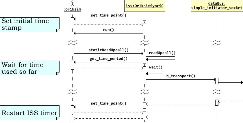 |
Figure 8.2. Sequence diagram for the Or1ksim SoC with synchronized timing, showing the timing calls.
Three additional functions are needed in the Or1ksim library to
support synchronized timing. The UART will need to know the clock
rate of the model (to work out the baud rate from the value of the
divisor latch). The Or1ksimSyncSC class
itself will need a pair of functions, one to set a timing point in
the ISS the second to return the amount of time since the last
timing point. This the amount of time the underlying ISS has used
when synchronizing with SystemC.
The three additional functions are simple additions. The clock rate is a configuration parameter, while a run time count of instructions executed is already maintained. An extra record in the run-time structure allows a time to be recorded (in seconds through dividing the count by the clock rate), which can be compared in subsequent calls to give the ISS time used since the last time point[6].
unsigned long int or1ksim_clock_rate();
or1ksim_clock_rate returns the Or1ksim
ISS clock rate in Hz. This information will be used by the
UART to allow it to set its baud rate.
void or1ksim_set_time_point();
or1ksim_set_time_point records the current
ISS simulation time (clock cycles divided by clock rate) in
the run-time data structure.
double or1ksim_get_time_period();
or1ksim_get_time_period returns the time
in seconds since the last time point was set. This function is
needed to keep the SystemC model of time due to instruction set
processing accurate, both in the synchronous SoC and when
temporal decoupling is added later (see Chapter 9.
These functions are a standard part of the Or1ksim 0.3.0 and Or1ksim 0.4.0 libraries.
The new module class, Or1ksimSyncSC is derived
from the existing Or1ksimExtSC module
class. The header of the base class,
Or1ksimExtSC is included and the new class
derived from that base class.
#include "Or1ksimExtSC.h"

class Or1ksimSyncSC
  : public Or1ksimExtSC
{
A custom constructor must be defined, but has the same arguments as the base class constructor, to which it will pass its arguments.
The new Or1ksim library call to give the clock rate is wrapped by a public function[7].
unsigned long int getClockRate();
The virtual function, doTrans function is
reimplemented—it will replace the call to
doTrans in the base class to add timing
synchronization.
The definition of the Or1ksim ISS wrapper module class with
synchronized timing, Or1ksimSyncSC may be
found in sys-models/sync-soc/Or1ksimSyncSC.h in
the distribution.
The custom constructor passes its arguments directly to the base class
constructor. It then uses the Or1ksim library function,
or1ksim_set_time_point to set an initial time
point at the start of simulation. The first call to
or1ksim_get_time_period will return the time
since the ISS started.
The doTrans function (which is used for both
read and write) is extended from the version used with
Or1ksimExtSC to synchronize with the SystemC
clock.
There are two components to the time taken in this model, the time
taken by the Or1ksim ISS and the time taken in any
peripherals. At the time of an upcall, the SystemC wrapper thread
will not have yielded control since either initialization or the
last upcall, when a time point was set in the ISS using
or1ksim_set_time_point.
A call to or1ksim_get_time_period gives the
time used by the ISS in this period. This is used as the argument
to wait, allowing any other threads in the
SystemC world to run until the calculated simulation time is
reached.
wait( sc_core::sc_time( or1ksim_get_time_period(), sc_core::SC_SEC ));
At this time the blocking transport function of the simple initiator
socket is called with the payload and specifying a zero time offset
(since the call to wait means the thread is
synchronized with the SystemC clock).
  sc_core::sc_time  delay = sc_core::SC_ZERO_TIME;
  dataBus->b_transport( trans, delay );
On return, the delay parameter will have been
updated with any additional delay due to the transaction—in
this case an estimate of the number of cycles to read or write the
relevant UART register. This delay represents the additional time
modeled since this thread last called
wait. The thread should
wait for this time, to allow other threads to
catch up.
However, since this is a synchronized model, the target (which is
still part of this thread of control, just in a different object)
will have already called wait to model the time
taken to read or write. So in this case, delay
will still be zero on return.
The read or write is now complete. A new time point is set with
set_time_point before control is returned to
the ISS. The ISS will start measuring time from this start
point, ready for use in the next upcall.
or1ksim_set_time_point();
The utility getClockRate is a simple wrapper
for the underlying Or1ksim library function (see Section 8.3.1). It will be used in the main
program (see Section 8.6).
unsigned long int
Or1ksimSyncSC::getClockRate()
{
  return or1ksim_clock_rate();

}       // getClockRate()
The definition of the Or1ksim ISS wrapper module class with
synchronized timing, Or1ksimSyncSC may be
found in sys-models/sync-soc/Or1ksimSyncSC.cpp
in the distribution.
[6] This is a loosely timed model. The timing from the ISS is approximate—it does not model the microarchitecture in detail. Cycle estimates will not be exact—that requires a fully cycle accurate model.
[7] The use of unsigned long int reflects the usage in the Or1ksim ISS. The designers do not anticipate usage to model designs in excess of 4GHz!
A new class, UartSyncSC derived from
UartSC implements the additional functionality
for synchronized timing.
The time taken for the serial pulses (start, data, parity, stop bits) on the real UART will be modeled as a delay before writing data onto the Tx output port. The corresponding delay on the Rx buffer port will be modeled by the terminal writing into that port[8].
The TLM 2.0 socket modeling the bus is extended to model the time taken for reads to and writes from the bus.
The class definition (in UartSyncSC.h) includes
the header of the base class and defines two new constants to
represent the delay in reading and writing in nanoseconds.
#define UART_READ_NS       60   // Time to access the UART for read
#define UART_WRITE_NS      60   // Time to access the UART for write
The class is derived directly from the base class,
UartSC. A new custom constructor is needed,
with an additional parameter specifying the input clock rate. This
is used in conjunction with the divisor latch to specify the baud
rate.
  UartSyncSC( sc_core::sc_module_name  name,
              unsigned long int        _clockRate,
              bool                     _isLittleEndian );
The busThread thread is reimplemented to add the
timing delay (as a call to wait in
transmitting a character as described above).
The blocking transport function, busReadWrite
is reimplemented to add in the bus delays in reading and
writing. Again this will be achieved by calls to
wait, so keeping the model synchronous.
The busWrite must also be reimplemented, since
any change to the divisor latch or the line control register (which
specifies the bit format being sent on the wire) could affect the
baud rate and timing for busThread
A new utility function, resetCharDelay is
defined to compute the delay in putting a character on the Tx port
from the clock rate, divisor latch and line control register.
Two new member variables are declared, to hold the clock rate and the calculated delay to put a character on the Tx port.
The implementation of the UART module class with synchronized
timing, UartSyncSC may be found in
sys-models/sync-soc/UartSyncSC.h in the
distribution.
The custom constructor passes the name and
_isLittleEndian flag to the base class
constructor. The clock rate is saved in the state variable,
clockRate.
UartSyncSC::UartSyncSC( sc_core::sc_module_name  name,
                        unsigned long int        _clockRate,
                        bool                     _isLittleEndian ) :
  UartSC( name, _isLittleEndian ),
  clockRate( _clockRate )
{

}       /* UartSyncSC() */
The new version of busThread adds only one
line to the version in the base class. A call to
wait( charDelay ) is added when the
transmit request is received (notified on the SystemC event,
txReceived).
    wait( txReceived );                         // Wait for a Tx request
    wait( charDelay );                          // Wait baud delay
    tx.write( regs.thr );                       // Send char to terminal
The new version of busReadWrite draws most of
its functionality from the base class version. However it then
synchronizes with a time delay for the read or write access. Since
the thread is now synchronous, a time delay of zero is returned with
the transaction.
void
UartSyncSC::busReadWrite( tlm::tlm_generic_payload &payload,
                          sc_core::sc_time         &delay )
{
  UartSC::busReadWrite( payload, delay );       // base function

  switch( payload.get_command() ) {
  case tlm::TLM_READ_COMMAND:
    wait( sc_core::sc_time( UART_READ_NS, sc_core::SC_NS ));
    delay = sc_core::SC_ZERO_TIME;
    break;

    <code for write commands etc>
The new version of busWrite similarly relies
on the base class for most of its functionality.
void
UartSyncSC::busWrite( unsigned char  uaddr,
                      unsigned char  wdata )
{
  UartSC::busWrite( uaddr, wdata );
However any change to the divisor latch or line control register could change the baud rate or the number of bits in each Tx transmission, and hence the modeled delay to send a character.
The function identifies if this has happened and if so calls
resetCharDelay to recalculate the delay.
  switch( uaddr ) {
  case UART_BUF:                // Only change if divisorLatch update (DLAB=1)
  case UART_IER:
    if( isSet( regs.lcr, UART_LCR_DLAB ) ) {
      resetCharDelay();
    }
    break;

  case UART_LCR:
    resetCharDelay();           // Could change baud delay
    break;
The time taken to put a character on the Tx line is the product of the time taken to put one bit on the line (the inverse of the baud rate) and the bits required for the character (start bit, data bits, optional parity bit, stop bit(s)). The baud rate is determined by the input clock rate and the 16-bit divisor latch.
| Note |
|---|---|
The divisor latch for a 16450 divides the input clock to yield an internal clock 16x the baud rate (i.e. not the actual baud rate itself). The 16450 specification supports an input clock up to 24 MHz, so the 16 bit divisor latch can yield an internal clock for rates down to 50 baud. However for a software model this limitation can be ignored. Faster input clocks can be specified, but it will not be possible to configure a 16-bit divisor latch for very low baud rates. |
The number of bits to send a character is determined by the line
control registers. There is always a stop bit, there can be 5-8 data
bits, an optional parity bit and 1, 1.5 or 2 stop bits. The
resetCharDelay function calculates the total
delay.
The implementation of the UART module class with synchronized
timing, UartSyncSC may be found in
sys-models/sync-soc/UartSyncSC.cpp in the
distribution.
[8] This is not the ideal solution. The delay is really a property of the channel, so should be modeled by a derived class of the standard SystemC buffer which provides a defined delay between data being written and data availability being signaled. The approach used here (transmitter models the delay) represents a practical compromise.
A new class, TermSyncSC derived from
TermSC implements the additional functionality
for synchronized timing.
As with the UART (see Section 8.4), the terminal will model the time taken to put the bits of a character on its Tx port. This mirrors the arrangement with the UART, so when the two are connected, delays in both directions are correctly modeled.
The new class, TermSyncSC is derived from
TermSC. The header for that class is included
and the new class derived from it.
#include "TermSC.h"

class TermSyncSC
  : public TermSC
{
A new custom constructor is needed, which takes a second argument to specify the baud rate.
  TermSyncSC( sc_core::sc_module_name  name,
              unsigned long int        baudRate );
The xtermThread thread will be
reimplemented. No further derived classes are anticipated, so this
function is declared private and not marked as
virtual.
A variable is needed to hold the baud rate. For convenience the class does not hold the baud rate, but the corresponding delay that this represents in sending a character.
sc_core::sc_time charDelay;
The definition of the terminal module class with synchronized
timing, TermSyncSC may be found in
sys-models/sync-soc/TermSyncSC.h in the
distribution.
The custom constructor calls the base class constructor to set the module name. The body of the constructor calculates the delay due to the baud rate. There is no configurability (this terminal supports 1 start, 8 data, 0 parity and 1 stop bits only), so this is a one off calculation.
TermSyncSC::TermSyncSC( sc_core::sc_module_name  name,
                        unsigned long int        baudRate ) :
  TermSC( name )
{
  charDelay = sc_core::sc_time( 10.0 / (double)baudRate, sc_core::SC_SEC );

}       /* TermSyncSC() */
The xtermThread thread is almost identical to
the base class version. A single line is added after the character
is read from the xterm and before it is written to the port
to add the modeled baud rate delay.
    int ch = xtermRead();               // Should not block

    wait( charDelay );                  // Model baud rate delay
    tx.write( (unsigned char)ch );      // Send it
The implementation of the terminal module class with synchronized
timing, TermSyncSC may be found in
sys-models/sync-soc/TermSyncSC.cpp in the
distribution.
As with the untimed SoC (see Section 7.5.1), the main program includes the headers for TLM 2.0 and the component modules, but this time using the synchronously timed versions.
#include "tlm.h"
#include "Or1ksimSyncSC.h"
#include "UartSyncSC.h"
#include "TermSyncSC.h"
The baud rate for the terminal is defined as a constant for convenience.
#define BAUD_RATE 9600
As before the main program (sc_main) takes as
arguments the Or1ksim configuration file and OpenRISC 1000 image. Instances
of the three modules are declared, but now have additional
arguments. The UART requires an input clock rate—obtained from
the ISS via the Or1ksimSyncSC public utility
function, getClockRate (see Section 8.3.3). The Terminal requires its baud
rate to be set.
  Or1ksimSyncSC  iss( "or1ksim", argv[1], argv[2] );
  UartSyncSC     uart( "uart", iss.getClockRate(), iss.isLittleEndian() );
  TermSyncSC     term( "terminal", BAUD_RATE );
The remainder of the program, connecting components and starting the simulation is identical to the untimed version.
The implementation of the main program for the SoC model with
synchronized timing may be found in
sys-models/sync-soc/syncSocMainSC.cpp in the
distribution.
The complete program is compiled from the top level make
file. Both a standalone program (simple-soc)
and a libtool compliant library
(libsimple-soc.la) are created, and both
incorporate the library created when building the logger test (see
Section 5.6). The library provides a
convenient mechanism for reusing the code from this model, when
creating subsequent models which used derived classes.
The Or1ksim configuration is also unchanged. Like the logger, the UART registers start at address 0x90000000 and are a total of 8 bytes in length.
Running the model requires specifying the configuration file
(unchanged) and the binary executable (this time the UART loop
back program). Assuming the programs have been built in a directory
named build, the following command line is
suitable.
.build/sysc-models/sync-soc simple.cfg progs_or32/uart-loop
Once again the xterm terminal should appear. Select it and type some characters. The window running the model, will show the logged output from the terminal, reporting the same characters being written and timing of the reads and writes. However this time, the time progresses as the characters are written, as shown in Figure 8.3.
$ .build/sysc-models/sync-soc simple.cfg progs_or32/uart-loop

             SystemC 2.2.0 --- May 16 2008 10:30:46
        Copyright (c) 1996-2006 by all Contributors
                    ALL RIGHTS RESERVED

   ... <Or1ksim initialization messages>

Char F read at  415740466667 ps
Read: 'F'
Char written at 416796660 ns
Char a read at  451075036667 ps
Read: 'a'
Char written at 452131230 ns
Char r read at  516688386667 ps
Read: 'r'
Char written at 517744580 ns

   ... <Lots more output>
Figure 8.3. UART loop back program log output.
The read timing is as the character leaves the terminal, after the terminal has added the baud rate delay. The write timing is as the character leaves the UART after the echo loop in the embedded application on the Or1ksim ISS and after the UART has added the baud-rate delay. So the timing from the read message to the write message should be the time for the UART delay for the current baud rate and packet bits, plus the execution time for the code to echo the character on the Or1ksim ISS.
The UART was initialized to use 1 start bit, 8 data bits and 1 stop bit, which at 9600 baud takes around 1040μs. The time shown in Figure 8.3 for the first character to be read and written back is approximately 1056μs. This seems reasonable, allowing approximately 1600 cycles (16μs at 100MHz) for the Or1ksim ISS to process the read and write code.
In this case study temporal decoupling is added to the TLM 2.0 model of a SoC. The SoC model with arbiter from the previous example is reused.
The code for the decoupled Or1ksim ISS wrapper
(Or1ksimDecoupSC.cpp and
Or1ksimDecoupSC.h), the code for the decoupled
UART module (UartDecoupSC.cpp and
UartDecoupSC.h) and the main program for the
complete model (decoupSocMainSC.cpp) may be founded
in the sysc-models/decoup-soc directory of the
distribution.
The idea of temporal decoupling is very simple and has been around for a long time (see for example A loosely coupled parallel LISP execution system. ). In a parallel system, the various threads keep their own local time, and only synchronize when they need to communicate with each other. It is particularly suited to timed-based modeling, since it ensures that no one thread hogs the execution.
It is worth noting that temporal decoupling does not improve overall model performance per se. All the same elements will need to be modeled. However it does ensure that the various threads in the model stay approximately in step over the duration of the run, making for a more realistic model. In our example it ensures that the Or1ksim model yields control regularly to allow the UART and terminal models to keep up.
TLM 2.0 provides some convenience classes to help threads implement temporal decoupling. The nomenclature used by these classes can be more than a little confusing—the following should help to explain how the technique works.
There are two key points about temporal decoupling.
Temporal decoupling is a property of threads, not module classes. So it is each thread that must keep track of its local view of time.
Nothing in the TLM 2.0 system checks a program is following the rules. It is up to each thread to ensure it is compliant.
Not all threads need use temporal decoupling, although the more that do, the greater the potential benefit. In general temporal decoupling is only appropriate for threads using TLM 2.0 blocking interfaces for their communication—typically loosely timed models. Where temporal decoupling is implemented it is managed by the threads driving initiator sockets.
TLM 2.0 defines four different timing entities to describe temporal decoupling. These are illustrated in Figure 9.1.
This represents the time unit on which all threads synchronize. For example a Global Quantum of 100μs means that all threads synchronize on 100μs 200μs, 300μs etc. Although the TLM 2.0 standard refers to this as just the Global Quantum, it is a system wide concept and for clarity this application note refers to it as the System Global Quantum.
This represents the time unit on which a particular thread synchronizes. The TLM 2.0 standard allows different threads to have their own private time unit of synchronization, which is very confusingly also referred to in the standard as the Global Quantum.
To avoid confusion, in this application note, the term Thread Global Quantum is used to mean the global quantum used by a particular thread.
Having different values for the global quantum in different threads is a recipe for complete confusion, while offering few advantages. The user is strongly recommended to set the Thread Global Quantum to the same value as the System Global Quantum when the thread is created and not change it.
For each thread, this represents the time remaining from the
current SystemC time (as returned by
sc_time_stamp) until the end of the
current Thread Global Quantum.
For example if the current SystemC time stamp is 235μs and the Thread Global Quantum is 100μs, then the Local Quantum will be 65μs—the time until the 300μs Thread Global Quantum synchronization is due.
If the recommendation that all threads set their Thread Global Quantum to be the same as the System Global Quantum is followed, then the value of the Local Quantum will be the same in all threads.
Each thread is allowed to hold a local view of time, which runs ahead of the current SystemC time. This is known as the Local Time Offset
The Local Time Offset must not take the thread's local view of time past the next Thread Global Quantum, i.e. it cannot exceed the Local Quantum.
For example if the current SystemC time stamp is 235μs and the Thread Global Quantum is 100μs, then a local time offset of 45μs would represent a thread local effective time of 280μs.
TLM 2.0 defines a singleton class[9] which can be used to hold the system global quantum. A set of functions to manipulate the system global quantum are provided.
instance
Returns a reference to the singleton global quantum object
set
Sets the system global quantum (as a SystemC
sc_time object)
get
Returns the value of the system global quantum
compute_local_quantum
Returns the local quantum, i.e. the time from the current SystemC time stamp to the next multiple of the system global quantum.
The intention is that at start up the main program should set the
system global quantum in the singleton
tlm_global_quantum object. All threads can then
set their thread global quantum by getting the value from the
tlm_global_quantum object.
TLM 2.0 provides a utility class for threads to keep track of their
thread global quantum, local quantum and local time offset. This is
in the tlm_utils namespace (like the convenience
sockets) with a header in
tlm_utils/tlm_quantumkeeper.h.
A module will instantiate one quantum keeper for each thread that uses temporal decoupling, initializing them in the constructor.
Two functions are provided to manage the thread global quantum:
set_global_quantum to set the value and
get_global_quantum. Typically a module
constructor will get the system global quantum
with a call to the singleton
tlm_global_quantum and immediately use that
to set the thread global quantum for each thread's quantum
keeper.
One function is provided to manage the local quantum. The
reset function calls
compute_local_quantum to calculate the local
quantum from the time stamp and the global quantum (which is done by
calling the compute_local_quantum in the
singleton tlm_global_quantum object) and sets
the local time offset to zero.
Typically a constructor will call reset for
each thread immediately after setting the thread global
quantum. The compute_local_quantum in the
quantum keeper is protected, so cannot be called
directly (which seems to be an omission). If the value of the local
quantum is needed, this can be obtained using the
compute_local_quantum function in the
singleton tlm_global_quantum object.
Four functions are provided to manage the local time
offset. set sets the local time offset to a
particular value, inc increments by a given
value and get_local_time returns the current
value of the local time
offset. get_current_time computes the local
effective time, i.e. the SystemC time stamp plus the local time
offset[10]. The intention is that a thread advances model time, it
will call set and inc
to update the local decoupled view of time.
Two functions are provided to handle synchronization. The test
need_sync returns true if the local time offset
exceeds the local quantum. sync calls
wait for the local time offset, synchronizing
the thread with the global SystemC view of time, and allowing
other threads to catch up. It then calls reset
to update the local quantum and zero the local time
offset. sync should always be called when
need_sync is true, but may be called at any
other time if required.
TLM 2.0 presents one model of temporal decoupling, with an explicit regular synchronization time.
Other temporal decoupling models can build on the TLM 2.0
infrastructure, for instance to remove the regular synchronization
time, and instead only synchronize when the local time offset
reaches some prescribed maximum. A class derived from the
tlm_gatekeeper class can modify the control
and synchronization functions, to allow different approaches to be
tried.
Temporal decoupling is not for use everywhere. These guidelines may help.
Use temporal decoupling for models based on blocking transactions, as used for loosely timed models. There is no obvious value to temporal decoupling in non-blocking models.
Only apply temporal decoupling to threads that are communicating via TLM 2.0 transactions. Other SystemC protocols (for example via FIFO) have no way of communicating delays between threads (the equivalent of the delay parameter in TLM 2.0 transport functions).
Let the thread controlling the initiator manage the temporal decoupling and synchronization. Targets should just return the incremented delay, and avoid synchronizing if possible.
Allocate one quantum keeper for each thread that drives an initiator socket and is implementing temporal decoupling.
Ensure that the thread global quantum is always the same as the system global quantum.
Select a global quantum that is small enough not to swamp timing behavior of the system. For example in the SoC used in this application note, the finest time granularity that matters is the time to put a character over a 9600 baud link, approximately 1ms. A time around 10-50% of this would be a reasonable time to use as a global quantum.
The key aspects of the overall decoupled SoC model are captured in a UML class diagram and a UML sequence diagram, showing interaction with the quantum keeper during processing.
The overall class diagram for the decoupled SoC design incorporating a UART and terminal is shown in Figure 9.2. The design is similar to that for the synchronized SoC (see Section 8.2.1). The Or1ksim ISS wrapper and UART are both subclassed to add the behavior needed for decoupled timing. There is no need to subclass the terminal module, since it has no TLM interface, and so therefore cannot use decoupling.
The new Or1ksimDecoupSC class is associated
with both the system global quantum keeper (tgq)
and the quantum keeper for the ISS thread
(issQk).
A sequence diagram, illustrating the behavior of the Or1ksim wrapper and its interaction with the quantum keepers for the design is shown in Figure 9.3. Only the operations of the wrapper and quantum keepers are sown, since there is no significant change in the interactions of the UART and terminal (see Section 7.1.2).
Where before, calls to wait were used to
enforce synchronized timing, this time the sync
function of the ISS gatekeeper is used to ensure a consistent view
of time. Rather than being held in strict synchronization, the
threads are allowed to catch up at least at each system global
quantum boundary.
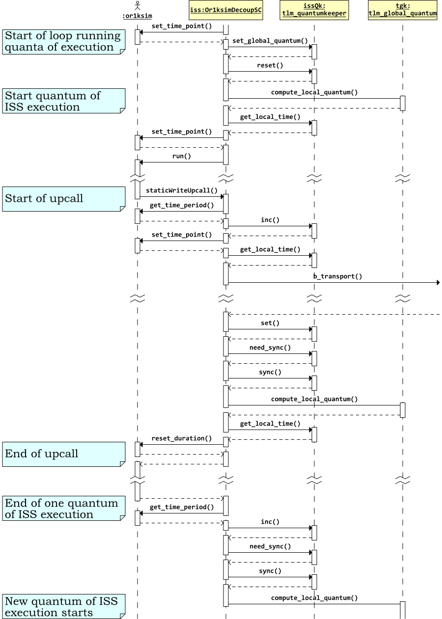 |
Figure 9.3. Sequence diagram for the Or1ksim SoC with decoupled timing, showing interaction with the quantum keepers.
The only thread that can be decoupled in the current model is the
Or1ksim wrapper class, Or1ksimDecoupSC, since
it is the only thread with a TLM 2.0 initiator socket.
ISS are natural candidates for temporal decoupling, since they often can run large blocks of code without any need for hardware interaction. This is particularly important for modern compiling ISS (e.g ARM SystemGenerator, ARC xISS), which achieve their performance by executing thousands of instructions at a time.
The changes needed to add temporal decoupling are:
Change the main thread, run so that it only
tries to execute instructions up to the end of the current global
quantum.
Change the upcall transport function,
doTrans, so that it increments the local
time offset, rather than synchronizing via
wait.
Updates to the Or1ksim ISS library to support running to a fixed time point.
A new class, Or1ksimDecoupSC is derived from
Or1ksimSyncSC to implement the required
functionality.
One additional function is needed in the Or1ksim library to
support temporal decoupling. The or1ksim_run
already allows the user to specify a duration for which the
simulation will run. A function, is added to change the duration of a
run already in progress.
void or1ksim_reset_duration( double duration );
or1ksim_reset_duration resets the
duration of a call to or1ksim_run which
is already in progress. The argument is the duration for which
the run should continue from the current
time (i.e. not from the time of the original call to
or1ksim_run).
This function is needed because upcalls may lead to a synchronization, increasing the time for which the ISS may run before needing resynchronization.
This function is a standard part of the Or1ksim 0.3.0 and Or1ksim 0.4.0 libraries.
The new class, Or1ksimDecoupSC is derived
from or1ksimSyncSC, whose header it
includes. A custom constructor is defined with the same arguments as
the base class constructor.
The ISS thread, run and the transport
function, doTrans are both reimplemented to add
temporal decoupling.
A pointer to the system global quantum, tgq, and
a quantum keeper for the ISS thread, issQk are
defined.
  tlm::tlm_global_quantum      *tgq;
  tlm_utils::tlm_quantumkeeper  issQk;
The definition of the Or1ksim ISS wrapper module class with
decoupled timing, Or1ksimDecoupSC may be
found in
sys-models/decoup-soc/Or1ksimDecoupSC.h in the
distribution.
The constructor passes its arguments to the base class,
Or1ksimSyncSC. The quantum keeper for the
ISS thread is then initialized with the system global quantum and
the local quantum calculated and local time offset zeroed with a
call to reset.
  tgq = &(tlm::tlm_global_quantum::instance());

  issQk.set_global_quantum( refTgq.get() );
  issQk.reset();
| Note |
|---|---|
The global quantum accessor function,
|
The main thread function, run is reimplemented
to ensure that the ISS simulation does not run past the end of the
current quantum. Instead of running for ever
(or1ksim_run( -1.0 );), the ISS is
run for the local time quantum, less the local time offset. This
means the ISS will return exactly at the point when it should need
to synchronize again.
The body of the program is a perpetual loop, which calculates the time left until the next global quantum then calls the ISS for that period.
  while( true ) {
    sc_core::sc_time  timeLeft =
      tgq->compute_local_quantum() - issQk.get_local_time();
On return, or1ksim_get_time_period is used to
find out how much computation has actually been carried out and
advance local time accordingly. This may be different to the
duration requested, since an upcall may set a new time point and
adjusted the duration. A new time point is immediately set ready for
the next loop.
    (void)or1ksim_run( timeLeft.to_seconds());

    issQk.inc( sc_core::sc_time( or1ksim_get_time_period(), sc_core::SC_SEC ));
    or1ksim_set_time_point();
If the local time offset has reached the end of the global quantum,
the thread synchronizes. This replaces the call to
wait in the synchronized version of the model
(Chapter 8).
    if( issQk.need_sync() ) {
      issQk.sync();
The transport function, doTrans has the same
structure as the synchronous version in the base class. However
instead of calling wait to delay calculation,
it updates the local time offset. The time offset is advanced for
the ISS simulation since the last time point and a new time point
is set.
  issQk.inc( sc_core::sc_time( or1ksim_get_time_period(), sc_core::SC_SEC ));
  or1ksim_set_time_point();
The delay argument to the blocking transport is the local time offset. This may be increased by the target (to model read/write delay), and the new value becomes the local time offset on return.
  sc_core::sc_time  delay = issQk.get_local_time();
  dataBus->b_transport( trans, delay );
  issQk.set( delay );
At this point synchronization could be required—the read/write delay could have pushed the local time offset past the global quantum.
  if( issQk.need_sync() ) {
    issQk.sync();
  }
The duration remaining for the ISS simulation is reset in the same way as in the main thread to be the local quantum less the local time offset. On return the ISS will continue for that period.
  sc_core::sc_time  timeLeft      =
    tgq->compute_local_quantum() - issQk.get_local_time();

  or1ksim_reset_duration ( timeLeft.to_seconds() );
The implementation of the Or1ksim ISS wrapper module class with
decoupled timing, Or1ksimDecoupSC may be
found in
sys-models/decoup-soc/Or1ksimDecoupSC.cpp in
the distribution.
Although the threads in the UART class are not temporarily
decoupled, a small modification is needed. The callback for the target
socket is part of this class, and it must handle delay data for the
initiator in Or1ksimDecoupSC suitably.
A new class, UartDecoupSC, derived from
UartSyncSC is defined to provide a modified
TLM 2.0 convenience target socket blocking callback function.
The class definition includes the header of the base class and is
derived from it. The constructor has the same parameters as the base
class, UartSyncSC.
A reimplemented version of the TLM 2.0 convenience callback,
busReadWrite is defined with the same
parameters as the base class function.
The definition of the UART module class with decoupled timing,
UartDecoupSC may be found in
sys-models/decoup-soc/UartDecoupSC.h in the
distribution.
The constructor just calls the base class constructor, passing on all its arguments.
The BusReadWrite callback has the same
structure as the version in the base class. Like the base class
it calls the original UartSC version to carry
out most of the functionality.
| Caution |
|---|---|
The call is therefore to the base class of the base
class of this class. The call cannot be to the base
class, since that would call |
The difference is in updating the delay. The synchronous base class waited to model the timing delay and set the delay in the response to zero. In this version the code just increments the delay (which is the local time offset) by the additional time to carry out the read or write.
  switch( payload.get_command() ) {

  case tlm::TLM_READ_COMMAND:
    delay += sc_core::sc_time( UART_READ_NS, sc_core::SC_NS );
    break;
The implementation of the UART module class with decoupled timing,
UartDecoupSC may be found in
sys-models/decoup-soc/UartDecoupSC.cpp in the
distribution.
The main program, decoupSocMainSC.cpp is similar
in structure to the main program used for the synchronous version (see
Section 8.6). This time the headers for the
versions of the Or1ksim wrapper and UART implementing temporal
decoupling are used and the time to use as the system global quantum
is defined as a parameter.
#include "Or1ksimDecoupSC.h"
#include "UartDecoupSC.h"
#include "TermSyncSC.h"

#define QUANTUM_US   100
Before any modules are instantiated, the system global quantum must be set. For the initial version a value of 100μs is selected, 10% of the time taken to transmit a character at 9600 baud, so there should be no awkward timing interactions.
tgq->set( sc_core::sc_time( QUANTUM_US, sc_core::SC_US ));
Thereafter the program follows the same structure (but using the versions of the Or1ksim wrapper and UART with temporal decoupling).
The implementation of the SystemC main program for the decoupled
SoC may be found in
sys-models/decoup-soc/decoupSocMainSC.cpp in the
distribution.
The complete program is compiled from the top level make
file. Both a standalone program (simple-soc)
and a libtool compliant library
(libsimple-soc.la) are created, and both
incorporate the library created when building the logger test (see
Section 5.6). The library provides a
convenient mechanism for reusing the code from this model, when
creating subsequent models which used derived classes.
The Or1ksim configuration is also unchanged. Like the logger, the UART registers start at address 0x90000000 and are a total of 8 bytes in length.
Running the model requires specifying the configuration file
(unchanged) and the binary executable (this time the UART loop
back program). Assuming the programs have been built in a directory
named build, the following command line is
suitable.
.build/sysc-models/decoup-soc simple.cfg progs_or32/uart-loop
The results look very similar to those for the synchronized version, as shown in Figure 9.4.
$ .build/sysc-models/decoup-soc simple.cfg progs_or32/uart-loop

             SystemC 2.2.0 --- May 16 2008 10:30:46
        Copyright (c) 1996-2006 by all Contributors
                    ALL RIGHTS RESERVED

   ... <Or1ksim initialization messages>

Char F read at  554441676667 ps
Read: 'F'
Char written at 555541610 ns
Char a read at  604641666667 ps
Read: 'a'
Char written at 605741610 ns
Char r read at  666641666667 ps
Read: 'r'
Char written at 667741600 ns

   ... <Lots more output>
Figure 9.4. UART loop back program log output with temporal decoupling.
The timing reported for the first character, 'F', is 1100μs—in the synchronized version it was 1056μs. The global quantum was set to 100μs, which means that other threads may have a delay of up to 100μs before they can run, affecting the time they will report for their actions.
If the quantum is changed from 100μs to 10ms, the change is more dramatic, as shown in Figure 9.5.
$ .build/sysc-models/decoup-soc simple.cfg progs_or32/uart-loop

             SystemC 2.2.0 --- May 16 2008 10:30:46
        Copyright (c) 1996-2006 by all Contributors
                    ALL RIGHTS RESERVED

   ... <Or1ksim initialization messages>

Char F read at  541041666667 ps
Read: 'F'
Char written at 551041600 ns
Char a read at  641041686667 ps
Read: 'a'
Char written at 651041620 ns
Char r read at  1471041676667 ps
Read: 'r'
Char written at 1481041600 ns
Figure 9.5. UART loop back program log output with temporal decoupling and 10ms global quantum.
The time taken to write the first character is now 10ms, completely dominated by the quantum. The typing of characters at the xterm is notably sluggish.
This is characteristic of loosely timed models with temporal decoupling. The objective is to model the gross behavior of the system with a reasonable view of the timing, such that events happen in the correct sequence. However detailed timing can be sacrificed in the interest of greater model performance.
The value for the global quantum is a subjective choice. In this case, with a busy polling UART loop back function, any delays were wasted in additional polling cycles, so a small quantum was appropriate.
In a more realistic scenario, the UART would be interrupt driven (or at least not polled continuously). Very likely the UART would only be lightly used, while other parts of the system were working. Under such circumstances, a global quantum of 100-500μs (10%-50% of the time to put one character on the UART) would be reasonable. The timing of characters output would be out by up to 100%, but the model would gain from fewer synchronizations.
In other scenarios an even higher quantum could be justified—for example if the UART were only for occasional diagnostic output, where sluggishness did not matter. However when modeling a 100MHz ISS as part of the SoC, the benefits of such large global quantum values would be minimal.
Beware that an excessively large quantum may break software with timing dependencies. It may mean that interrupt sequences do not arrive in a reasonable order, or flood in all at once. An example of this is shown in Chapter 10.
The other step to take to improve the system would be to move to an exclusively TLM 2.0 model. The SystemC buffer is a good way to model the UART to terminal connection. However by using a TLM 2.0 socket in each direction, the UART could adopt temporal decoupling, giving further improvement in the overall model.
[9] A singleton is a class of which only one instance can be created. The constructor is declared private (so no other class can create it), and a static function is provided to return the single instance. This static function will create the single instance the first time it is called, and thereafter just return a reference to that same instance.
Singleton classes are useful for holding centrally required values and providing centrally required functions in a system, where having duplicate provision would lead to incorrect behavior.
[10]
The naming is not
consistent. get_local_time should have
been just get for consistency with
set and
inc.
get_current_time would be better named
get_effective_time, to match its
description in the standard.
The Simple SoC used in the previous sections is not sufficient to run Linux. Two significant extensions are needed.
Memory management must be added to support Linux virtual memory. This is provided by enabling the internal MMUs (instruction and data) of the Or1ksim ISS.
The SystemC UART peripheral must be extended to handle interrupts.
The example design was shown in Section 3.1.3, but for convenience the diagram is repeated here in Figure 10.1.
Enabling memory management is a matter of modifying the configuration file for Or1ksim. The Linux port used here expects to boot from flash memory, so the internal memory of Or1ksim is also extended to provide this.
The UART model, UartDecoupSC is further
extended by a new derived class, UartIntrSC
providing a SystemC sc_out<bool> port
through which the interrupt signal is driven.
The code for the Or1ksim ISS wrapper with interrupts enabled
(Or1ksimIntrSC.cpp and
Or1ksimIntrSC.h), the code for the interrupt
enabled UART module (UartIntrSC.cpp and
UartIntrSC.h) and the main program for the complete
model (intrSocMainSC.cpp) may be found in the
sysc-models/intr-soc directory of the distribution.
The key aspects of the overall decoupled SoC model are captured in a UML class diagram and a UML sequence diagram, showing how an interrupt is processed during a write transaction to the UART.
The overall class diagram for the SoC with interrupts incorporating a UART and terminal is shown in Figure 10.2. The design is similar to that for the temporally decoupled SoC (see Section 9.3.1). The Or1ksim ISS wrapper and UART are both subclassed to add the behavior needed for interrupt handling. There is no need to subclass the terminal module, since it has no interrupts to be modeled.
The new Or1ksimIntrSC class is associated
with an array of 32 signals, which may be connected to peripherals
wishing to raise an interrupt.
The new UartIntrSC class is associated with a
SystemC FIFO used to collect interrupts raised from both Rx and
Tx ports. It also has a SystemC output port,
intr on which it drives any interrupt it raises.
A sequence diagram, illustrating how the Or1ksim wrapper handles an interrupt when a character is written to the UART is shown in Figure 10.3. Only the interaction between the wrapper and the UART is shown, since the other components largely retain their existing functionality. The model is fully decoupled, but for compactness the actions to handle decoupled timing are omitted.
The Or1ksim wrapper maintains a separate process (a SystemC
SC_METHOD) to handle interrupts. Similarly the
UART adds a new thread to handle interrupts. Although not standard
UML separate threads of control are shown for each of these
objects in the sequence diagram.
The Or1ksim ISS library is extended to provide
API calls to generate an interrupt. The Or1ksim
includes a programmable interrupt controller
(PIC), which is enabled. The new
API call, or1ksim_interrupt,
provides an edge-triggered interrupt, and takes as parameter the
interrupt number to be triggered. The new API
calls, or1ksim_interrupt_set and
or1ksim_interrupt_set, provide for setting and
clearing level sensitive interrupts. The choice of interrupt type to
use is made in the Or1ksim configuration file.
The Or1ksim wrapper, Or1ksimDecoupSC is further
extended by a new derived class, Or1ksimIntrSC,
which provides an array of signal ports to connect to external devices
which wish to generate interrupts.
The additional function allows the external SystemC model to call into the Or1ksim ISS to request an interrupt. The ISS requires that interrupts are not taken mid-instruction (for example while a peripheral memory access upcall is in progress), so a flag is set internally, allowing the ISS to trigger the interrupt at the start of the next instruction.
The standard version of Or1ksim uses edge triggered interrupts, and they are used in this example. However Or1ksim can support level triggered interrupts. For this additional interface functions are provided, although they are not used in this example.
void or1ksim_interrupt( int i );
or1ksim_interrupt requests the the
interrupt given by its argument be taken at the start of the
next instruction cycle. This is edge-triggered interrupt
functionality, and there is no need to clear the interrupt.
void or1ksim_interrupt_set( int i );
or1ksim_interrupt_set asserts
the interrupt given by its argument for consideration by
Or1ksim at the start of the next instruction cycle. This is
for level triggered interrupt handling, and must be explicitly
cleared when the interrupt handling is complete.
void or1ksim_interrupt_clear( int i );
or1ksim_interrupt_clear deasserts the
interrupt given by its argument for consideration by Or1ksim
at the start of the next instruction cycle. This is to clear an
interrupt previously asserted with void
or1ksim_interrupt_set when using level triggered
interrupt handling.
or1ksim_interrupt requests the
interrupt given by its argument be taken at the start of the
next instruction cycle.
These functions are a standard part of the Or1ksim 0.3.0 and Or1ksim 0.4.0 libraries.
The new module class, Or1ksimIntrSC is
derived from the existing Or1ksimDecoupSC
module class, whose header, Or1ksimDecoupSC.h,
is included. The number of interrupts to be supported is given by
the constant, NUM_INTR.
#define NUM_INTR 32
The new class derived from the base class and a custom constructor
defined. The possible interrupts are represented by an array of
sc_signal.
sc_core::sc_signal<bool> intr[NUM_INTR];
![[Tip]](./images/tip.png) | Tip |
|---|---|
It would have been possible to define an array of signal input
ports, By creating actual signals, interrupts that are unused can be left unbound and ignored. |
A SystemC method is required to handle the interrupts (since it never waits, a thread is not needed). This can respond to interrupts in parallel with the main ISS execution thread.
void intrMethod();
The definition of the Or1ksim ISS wrapper module class with
interrupts, Or1ksimIntrSC may be
found in
sys-models/intr-soc/Or1ksimIntrSC.h in the
distribution.
The constructor passes its arguments to the base class constructor
for processing. It then sets up intrMethod as a
SystemC method process, sensitive to the positive edge of each
interrupt signal. There is no need to initialize this function.
  SC_METHOD( intrMethod );
  for( i = 0 ; i < NUM_INTR ; i++ ) {
    sensitive << intr[i].posedge_event();
  }
  dont_initialize();
The interrupt method is triggered by a positive edge on one of the
signals. It loops through to find which interrupt was triggered and
generates a call to or1ksim_interrupt for that
interrupt number. In principle more than one could be triggered in the
same cycle, so all are checked.
  for( i = 0 ; i < NUM_INTR ; i++ ) {
    if( intr[i].event()) {
      or1ksim_interrupt( i );
    }
  }
The implementation of the Or1ksim ISS wrapper module class with
interrupts, Or1ksimIntrSC may be found in
sys-models/intr-soc/Or1ksimIntrSC.cpp in the
distribution.
The existing UART module processes interrupts, but does not generate
an external interrupt signal. To generate an interrupt signal,
UartDecoupSC is further extended by a new
derived class, UartIntrSC, which provides a
signal port and a new thread to drive that signal port
An extra thread is required, because both the
rxMethod and busThread
processes may wish to drive signals, but SystemC requires that a
signal is driven by a single process. Just as in hardware design a
simple wire would not normally have more than one driver.
The new process communicates with the existing processes via a FIFO
internal to the UART, allowing rxMethod and
busThread to both request interrupt activity
and for those requests to be processed in the order they were
generated.
The new module class, UartIntrSC is
derived from the existing UartDecoupSC
module class, whose header, UartDecoupSC.h,
is included.
A custom constructor is declared, and a signal output port,
sc_out<bool> intr through which the
interrupt will be driven.
The new thread, intrThread is declared. It
will use re-implemented versions of the genIntr
and clrIntr functions from the base class,
UartSC.
A Boolean FIFO is used to hold the queue of requests from the
existing processes, rxMethod and
busThread.
sc_core::sc_fifo<bool> intrQueue;
The definition of the UART module class with interrupts,
UartIntrSC may be found in
sys-models/intr-soc/UartIntrSC.h in the
distribution.
Since this class declares a new SystemC process,
SC_HAS_PROCESS is used. The constructor passes
its arguments to the base class,
UartDecoupSC and sets the FIFO queue size to 1.
UartIntrSC::UartIntrSC( sc_core::sc_module_name  name,
                        unsigned long int        _clockRate,
                        bool                     _isLittleEndian ) :
  UartDecoupSC( name, _clockRate, _isLittleEndian ),
  intrQueue( 1 )
{
| Note |
|---|---|
The choice of FIFO size means that there should be only one
request for interrupt pending. In principle this could block an
attempt by the This is an explicit model design decision. If there is interrupt congestion, then it would be useful to know—indicating design issues over the UART capacity. If this were not an issue, then it would be quite valid to use a larger FIFO capacity. |
The constructor then creates the new SystemC method for
intrThread.
intrThread has a very simple
API. If true is read it
asserts an interrupt (drives the interrupt port
true), otherwise it deasserts the interrupt port
(drives the interrupt port false).
On initialization, the interrupt port is deasserted
(false). The thread then sits in a perpetual
loop, copying requests from the FIFO to the interrupt signal output
port.
  while( true ) {
    intr.write( intrQueue.read() );
  }
The interrupt generator, genIntr is almost
identical to the version in the base class,
UartSC. The only difference is that if an
interrupt is generated, a request to drive the signal is written
onto the internal interrupt FIFO for processing by the
intrThread thread.
    setIntrFlags();                    // Show highest priority
    intrQueue.write( true );            // Request an interrupt signal
The interrupt clear routing is a similar modification, this time
requesting the interrupt signal to be cleared by writing
false on the FIFO queue.
  if( isSet( regs.iir, UART_IIR_IPEND )) {     // 1 = not pending
    intrQueue.write( false );                   // Deassert if none left
The implementation of the UART module class with interrupts,
UartIntrSC may be found in
sys-models/intr-soc/UartIntrSC.cpp in the
distribution.
The main program for the model supporting interrupts is in
intrSocSC.cpp. It has a very similar structure to
the main program used with the temporal decoupling example in Section 9.6, but uses the new versions of the
Or1ksim wrapper class and UART module,
Or1ksimIntrSC and
UartIntrSC.
A baud rate of 115,200 is expected for the Linux kernel serial port and a global quantum of 10μs is appropriate for this. A constant is defined to hold the interrupt port number used by the UART (2).
#define BAUD_RATE   115200
#define QUANTUM_US      10

#define INTR_UART        2
The main program structure is unchanged, except that the UART interrupt output port needs to be connected to the correct signal in the Or1ksim wrapper:
uart.intr( iss.intr[INTR_UART] );
The code for the SystemC main program for the SoC with interrupts
may be found in
sys-models/intr-soc/intrSocMainSC.h in the
distribution.
Compilation and linking of the program follows the same procedure as previous examples.
As a simple test, the interrupt loop program used in earlier examples is extended to demonstrate basic interrupt handling. However the main test is booting a Linux kernel.
A simple test is provided in uart-loop-intr.c
as an extension of uart-loop.c. After a
character is read, the program loops to wait until the interrupt
pending flag is clear (indicating the transmit buffer is empty).
    do {                        /* Wait for interrupts to clear */
      ;
    } while( is_set( uart->iir, UART_IIR_IPEND ) );
This is a very basic test—if all is well it behaves identically to the existing loop program. If there is a problem clearing the transmit buffer empty interrupt, or the received data available interrupt is not cleared when data is read, then the program will lock up waiting for the interrupt pending flag to clear.
The source code for the interrupt driven UART program may be found
in progs-or32/uart-loop-intr.c in the
distribution. It is built using the standard OpenRISC 1000 tool chain as
part of the main system build.
This test uses a Linux 2.6.19 kernel built for the standalone
Or1ksim as described in
Embecosm Application Note 2. The OpenCores OpenRISC 1000 Simulator and
Tool Chain: Installation Guide.
[4]. A configuration file, which enables the
internal memory management units
(MMUs) and Programmable Interrupt Controller
(PIC) of the Or1ksim is provided,
linux.cfg. This also declares additional
internal memory space in Or1ksim for flash and
SRAM.
The SystemC model is then run with this configuration file and the Linux kernel binary.
./IntrSocSC linux.cfg ../linux-2.6.19/vmlinux
Initially Linux copies itself from flash memory to RAM.
Copying Linux... Ok, booting the kernel.
After a pause while initial booting is taking place the serial interface is ready, allowing the normal kernel boot messages to appear:
Linux version 2.6.19-or32 (jeremy@thomas) (gcc version 3.4.4) #59 Wed Jun 25 18:
48:06 BST 2008
Detecting Processor units:
  Signed 0x391
Setting up paging and PTEs.
write protecting ro sections (0xc0002000 - 0xc024c000)
Setting up identical mapping (0x80000000 - 0x90000000)
Setting up identical mapping (0x92000000 - 0x92002000)
Setting up identical mapping (0xb8070000 - 0xb8072000)
Setting up identical mapping (0x97000000 - 0x97002000)
Setting up identical mapping (0x99000000 - 0x9a000000)
Setting up identical mapping (0x93000000 - 0x93002000)
Setting up identical mapping (0xa6000000 - 0xa6100000)
Setting up identical mapping (0x1e50000 - 0x1fa0000)
dtlb_miss_handler c00040c8
itlb_miss_handler c00041a8
Built 1 zonelists.  Total pages: 3953
Kernel command line: root=/dev/ram console=ttyS0

   <Lots more Linux kernel messages...>

Serial: 8250/16550 driver $Revision: 1.90 $ 4 ports, IRQ sharing disabled
serial8250.0: ttyS0 at MMIO 0x90000000 (irq = 2) is a 16450

   <Lots more Linux kernel messages...>

VFS: Mounted root (ext2 filesystem) readonly.
Freeing unused kernel memory: 104k freed
init started:  BusyBox v1.4.1 (2007-03-22 18:53:56 EST) multi-call binary
init started:  BusyBox v1.4.1 (2007-03-22 18:53:56 EST) multi-call binary
Starting pid 22, console /dev/ttyS0: '/etc/init.d/rcS'

Please press Enter to activate this console.
This takes a simulated time of about 37 seconds, and on a modern PC an elapsed time of around 20-25 seconds (the Or1ksim ISS in this minimal configuration runs at 150-200MHz [11]).
At this point hitting return will start up a Linux shell, running some basic commands and in this example the BusyBox utilities (see the website for more details).
Please press Enter to activate this console.
Startingpid 25, console /dev/ttyS0: '/bin/sh'


BusyBox v1.4.1 (2007-03-22 18:53:56 EST) Built-in shell (ash)
Enter 'help' for a list of built-in commands.

# ls /proc
1              2              bus            iomem          self
10             25             cmdline        ioports        slabinfo
11             26             cpuinfo        kcore          stat
12             3              crypto         kmsg           sys
13             4              devices        loadavg        sysrq-trigger
14             5              diskstats      locks          sysvipc
15             6              driver         meminfo        tty
16             7              execdomains    misc           uptime
17             8              filesystems    mounts         version
18             9              fs             net            vmstat
19             buddyinfo      interrupts     partitions     zoneinfo
# busybox mount
rootfs on / type rootfs (rw)
/dev/root on / type ext2 (ro)
proc on /proc type proc (rw)
#
The importance of choosing a suitable value for the global quantum is well illustrated here. Rebuild the model with a global quantum of 100μs—rather longer than the time it takes to transmit one character at 115,200 baud.
#define QUANTUM_US 100
The time taken to boot is marginally faster (19s), but this time the terminal cannot cope with the erratic interrupt behavior.
VFS: Mounted root (ext2 filesystem) readonly.
Freeing unused kernel memory: 104k freed
init started:  BusyBox v1.4.
Please press Ent
The Linux serial driver loses interrupts and the system locks up and will eventually crash with an unhandled interrupt exception.
[11] This may seem exceptionally fast for an interpreting ISS, but this model is configured with slow RAM with a 20-25 cycle access time and no caches. So 150-200MHz represents only 5-10 MIPS. That's why booting a basic Linux kernel takes 37s of simulated time, rather than the 2-3s that might reasonably be expected!
All the models in previous chapters have considered only the main WishBone bus interface to the OpenRISC 1000. However the processor also provides a debug interface, which at the hardware level is implemented via a IEEE 1149.1 JTAG.
At the simplest level, it is easy to have a transactional view of JTAG. Registers are shifted in and registers are shifted out. A simple read-modify-write transaction.
The difficulty is that JTAG is a bit serial interface, whereas TLM 2.0 really models simple reads and writes over bus interfaces (such as WishBone). The solution is to represent the JTAG register in a byte vector, and use a TLM 2.0 generic payload extension to describe the JTAG specific characteristics of bit length and target action (reset, shift through the instruction register or shift through the data register). This is described in Section 11.2.
The example design extended to support JTAG was shown in Section 3.1.4, but for convenience the diagram is repeated here in Figure 11.1.
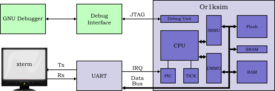 |
Figure 11.1. Simple SoC based on the OpenRISC 1000 Or1ksim with interrupts, MMU and JTAG debug interface.
For this example, a full debugger is not used to drive the JTAG
interface. Instead a simple JTAG logger,
JtagLoggerSC, is used. This initializes the
JTAG interface, then reads the Next Program
Counter (NPC) SPR once per second. This
is achieved by shifting a JTAG register for a debug unit
WRITE_COMMAND to specify the SPR to read, followed
by shifting a JTAG register for a debug unit
GO_COMMAND to read the actual register. This
simplified design is shown in Figure 11.2.
The Or1ksimIntrSC is extended with a new TLM 2.0
target port and handler for JTAG. This in turn requires a new TLM 2.0
generic payload extension class, JtagExtensionSC.
The code for the Or1ksim wrapper with JTAG interface
(Or1ksimJtagSC.cpp,
Or1ksimJtagSC.h), the code for the generic payload
extension (JtagExtensionSC.cpp,
JtagExtensionSC.h), the code for the JTAG logger
(JtagLoggerSC.cpp,
JtagLoggerSC.h) and the main program for the
complete model (jtagSocMain.cpp) may be found in
the sysc-models/jtoc-soc directory of the
distribution.
The key aspects of the overall decoupled SoC model are captured in a UML class diagram and a UML sequence diagram, showing how a transaction for the JTAG port is processed.
The overall class diagram for the SoC with JTAG debug support incorporating a UART, terminal and simple debug logger is shown in Figure 11.3. The design is similar to that for the SoC with interrupts (see Section 10.1.1). The overall diagram is now quite complex, so, for clarity, only those classes new to the JTAG enabled design are shown. The remaining detail was shown earlier in Figure 10.2.
The Or1ksim ISS wrapper is subclassed to add the new target port and handler for JTAG. This needs a SystemC mutex in order to ensure that access to the JTAG port does not clash with running of the underlying Or1ksim model. This is discussed in more detail in Section 11.2.
The new logger class, JtagLoggerSC provides a
simple stream of debug JTAG register transfers through the debug
TLM 2.0 interface. That interface makes use of the mandatory
extension class JtagExtensionSC to specify
details of the JTAG register being shifted.
A sequence diagram, illustrating how the Or1ksim wrapper handles a debug transaction is shown in Figure 11.4. Only the interaction between the wrapper and the JTAG debug interface is shown, since the other components largely retain their existing functionality. The model is fully decoupled and processes interrupts, but for compactness these details are not repeated here.
The key feature is the use of a SystemC mutex to ensure that the
JTAG transactions are only processed between calls to the
Or1ksim run method.
The SystemC TLM 2.0 generic payload is intended for use with models of conventional buses. The payload is a multiple of bytes long and transmitted over an interface that is a multiple of bytes wide.
This is not a good fit for bit-serial interfaces such as IEEE 1149.1 JTAG.
It is possible to build a completely new payload, customized to such an interface, and which would permit use of all the other TLM 2.0 infrastructure. However such a task is complex and time-consuming, and is not good for compatibility between models.
As an alternative, SystemC permits extension of the generic payload. There are two flavors of extension, ignorable extensions are used where the generic payload is still meaningful without the extension being present. Mandatory extensions are used where the information in the payload is essential to correct operation of targets and initiators.
Ignorable extensions are preferred wherever possible, since they maximize reusability of the interface. The C++ type system is used to enforce mandatory extensions, and their use requires sharing a defining type between all targets and initiators.
For the JTAG interface we use an ignorable extension. Where present, this specifies what type of transaction is required (reset, shift through the instruction register, shift through the data register) and the exact bit length of the register being shifted. The actual data is supplied as a byte vector in the generic payload as normal.
Where the extension data is not provided, the type of transaction is inferred from the generic payload's address: 0 for shifting through the instruction register, 1 for shifting through the data register and any other value for reset. The bit length is calculated as 8 times the generic payload data length.
In practice the extension will always be used, but by being ignorable, we allow the maximum possible reuse of the interface in applications.
The extension class is a subclass of the abstract SystemC template
class tlm::tlm_extension
class JtagExtensionSC: public tlm::tlm_extension<JtagExtensionSC>
The extension holds data on the JTAG access type required (reset, shift through the instruction register, shift through the data register) and the exact number of bits to be shifted. For long term compatibility a data field to request debug is added, although it is not used in this application note.
An enumeration type is specified to define the access type. This is public, since targets and initiators must be able to reference it.
  enum AccessType {
    RESET,
    SHIFT_IR,
    SHIFT_DR
  };
The constructor initializes the data fields to appropriate default values (type RESET, bit size zero, debug disabled).
JtagExtensionSC ();
It might be thought appropriate to have variants that could simultaneously initialize the arguments, allowing for easy dynamic allocation and destruction of extensions as needed. However allocation of the extension class is expensive in SystemC, and dynamic allocation is discouraged. Instead a single instance is typically allocated and reused.
Two virtual methods from the parent class must be implemented to allow instances to cloned and copied.
virtual tlm::tlm_extension_base* clone() const;
virtual void copy_from (tlm::tlm_extension_base const &ext);
The public interface to the extension is through its accessors, a pair for each data field.
AccessType  getType () const;
void        setType (AccessType _type);

int         getBitSize () const;
void        setBitSize (int  _bitSize);

bool        getDebugEnabled () const;
void        setDebugEnabled (bool  _debugEnabled);
The data itself is held privately within the class.
AccessType  type;
int         bitSize;
bool        debugEnabled;
The definition of the SystemC generic payload extension class for
JTAG, JtagExtensionSC, may be found in
sys-models/jtag-soc/JtagExtensionSC.h in the
distribution.
The constructor simply initializes the private data fields to default values (type RESET, bit size zero, debugging disabled).
The two virtual methods which must be implemented,
clone and copy_from use
boilerplate code from the TLM 2.0 language reference manual. This is
quite sufficient for a simple extension like this.
Finally the three pairs of accessor methods allow each field to be read or set.
The implementation of the SystemC generic payload extension class
for JTAG, JtagExtensionSC, may be found in
sys-models/jtag-soc/JtagExtensionSC.cpp in the
distribution.
The Or1ksim ISS library is extended to provide API calls to handle
JTAG registers being shifted in and out. The API
call, or1ksim_jtag_reset, causes the JTAG unit
to process through a reset sequence. The API
calls, or1ksim_jtag_shift_ir and
or1ksim_jtag_shift_dr, take a byte vector and bit
length as arguments and shift specified number of bits through the
instruction register and data register respectively.
All three API calls return the time taken by the function in seconds
(as a C++ double). A key aspect of this API is that the
calls may not be used during the execution of
or1ksim_run. This could occur during processing
of an upcall, but at such a time the processor is mid-instruction and
the state for debug unit processing is inconsistent. This requirement
is enforced in the wrapper by use of a SystemC
sc_mutex.
The Or1ksim wrapper, Or1ksimIntrSC is further
extended by a new derived class, Or1ksimJtagSC,
which provides a TLM 2.0 target port to for JTAG transactions and a
handler method, jtagHandler, for those
requests.
The JTAG target port makes use of TLM 2.0 generic payload with an
ignorable extension, used to specify precisely the JTAG operation
required and the size in bits of the JTAG register. The class
JtagExtensionSC (see Section 11.2) is defined for this purpose.
These additional functions allow the external SystemC model to call into the Or1ksim ISS to request debugging activity through use of a JTAG register. The ISS requires that interrupts are not taken mid-instruction (for example while a peripheral memory access upcall is in progress). However it is up to the caller to enforce this restriction.
JTAG registers are represented as a byte vector, with the least significant bits in the lowest numbered byte. Where the number of bits is not a multiple of eight, it is the most significant byte which holds the odd number of bits, shifted to the least significant position within the byte. Thus for a 12-bit register, bits 0-7 would be in byte 0 and bits 8-11 would be in the least significant 4 bits of byte 1.
double or1ksim_jtag_reset ();
or1ksim_jtag_reset requests the Or1ksim
ISS debug unit go through a JTAG reset cycle to put the
Test Access Port (TAP) in a consistent
state. It returns the time taken in seconds.
double  or1ksim_jtag_shift_ir (unsigned char *jreg,
			       int            num_bits);
or1ksim_jtag_shift_ir shifts the JTAG
register specified by its arguments through the JTAG
instruction register. It returns the time taken in seconds.
double  or1ksim_jtag_shift_dr (unsigned char *jreg,
			       int            num_bits);
or1ksim_jtag_shift_dr shifts the JTAG
register specified by its arguments through the JTAG data
register. It returns the time taken in seconds.
The behavior of the debug unit in response to JTAG register transfers is fully documented in descriptions of the Test Access Port [3] and the OpenCores Debug Unit [2].
These functions are a standard part of the Or1ksim 0.4.0 library.
| Caution |
|---|---|
These functions are not a standard part of the Or1ksim 0.3.0 library. |
The new module class, Or1ksimIntrSC is
derived from the existing Or1ksimIntrSC
module class, whose header, Or1ksimIntrSC.h, is
included.
The key addition to the public interface is a 1-bit wide TLM 2.0 target port for JTAG transactions.
tlm_utils::simple_target_socket&Or1ksimJtagSC, 1& jtag;
The constructor is identical in form to that of the base class, taking the same arguments. It will have more work to do, setting up the target TLM 2.0 port handler and clearing the mutex.
The protected virtual run method is
reimplemented in this class. Functionally it is very similar to the
base implementation, but a SystemC mutex is used to ensure that it
does not run while a JTAG transaction is being processed.
As described earlier (see Section 11.2), the JTAG transactional interface uses an ignorable payload extension. If this extension is not present, the address field of the generic payload is used to infer the action required. For convenience the addresses corresponding to the instruction and data registers are specified.
static const unsigned int  ADDR_SHIFT_IR = 0;
static const unsigned int  ADDR_SHIFT_DR = 1;
JTAG transactions cannot be processed while the underlying Or1ksim ISS is running. This is enforced using a SystemC mutex.
sc_core::sc_mutex or1ksimMutex;
Finally we need a handler for JTAG transactions that are received.
void  jtagHandler( tlm::tlm_generic_payload &payload,
                   sc_core::sc_time         &delay );
The definition of the Or1ksim ISS wrapper module class with JTAG
debug support, Or1ksimJtagSC may be found in
sys-models/jtag-soc/Or1ksimJtagSC.h in the
distribution.
The constructor passes its arguments to the base class. It then associates the JTAG target port with its handler and clears the mutex.
// Bind the handler to the JTAG target port.
jtag.register_b_transport( this, &Or1ksimJtagSC::jtagHandler );

// Unlock the Mutex
or1ksimMutex.unlock ();
The implementation of the run method is very
similar to the base class for temporally decoupled models (see Section 9.4.3). However the call to
or1ksim_run is surrounded by lock/unlock of the
mutex to ensure it cannot run at the same time as a thread
requesting JTAG access.
or1ksimMutex.lock ();
(void)or1ksim_run (timeLeft.to_seconds ());
or1ksimMutex.unlock ();
The handler for JTAG transactions attempts to determine the type and exact bit size of the register from the extension payload. If this is not present (it is an ignorable extension), then it uses the generic payload address and data length instead.
// Retrieve the extension.
JtagExtensionSC *ext;
payload.get_extension (ext);

// Check if the extension exists. Set up the access type and bit size as
// appropriate.
JtagExtensionSC::AccessType  type;
int                          bitSize;

if (NULL == ext)
  {
    unsigned int  addr = (unsigned int) payload.get_address ();

    type    = (ADDR_SHIFT_IR == addr) ? JtagExtensionSC::SHIFT_IR :
              (ADDR_SHIFT_DR == addr) ? JtagExtensionSC::SHIFT_DR :
                                        JtagExtensionSC::RESET ;
    bitSize = 8 * (int) payload.get_data_length ();
  }
else
  {
    type     = ext->getType ();
    bitSize = ext->getBitSize ();
  }
The handler then calls the appropriate function in the Or1ksim
ISS, surrounding the call by a mutex lock/unlock, to ensure that
JTAG transactions are not processed while the ISS is
running. This could occur if an upcall caused a
wait () allowing processing of a JTAG
transaction to occur.
The implementation of the Or1ksim ISS wrapper module class with
JTAG debug support, Or1ksimJtagSC may be
found in sys-models/jtag-soc/Or1ksimJtagSC.cpp
in the distribution.
In normal use, a debugger, such as GDB would be connected to the JTAG port. For demonstrating the interface, we use a stripped down JTAG logger class. This uses the debug interface to read the processor's next program counter SPR once per (modeled) second.
With the Or1ksim debug unit (see [2]), this requires the following steps.
Reset the JTAG interface
Shift DEBUG (0x8) into the JTAG instruction
register.
Construct a JTAG data register to select module
CPU0 so we can access its SPRs and shift that
into the JTAG data register.
Construct a JTAG data register for the
WRITE_COMMAND debug unit command, specifying
that we wish to read the next program counter SPR and shift that
into the JTAG data register.
Construct a JTAG data register for the
GO_COMMAND debug unit command, to collect the
value read from the next program counter SPR and shift that into
the JTAG data register.
These last two steps are repeated with a wait of one second between, to give a regular report on the value of the next program counter.
The logger will require a simple TLM 2.0 initiator socket, which
will use the generic payload with a custom extension,
JtagExtensionSC. The relevant headers are
included.
#include <tlm.h>
#include <tlm_utils/simple_initiator_socket.h>

#include "JtagExtensionSC.h"
The logger declares an initiator TLM 2.0 port to connect to the target port in the Or1ksim wrapper. This is the public interface to this module.
tlm_utils::simple_initiator_socket<JtagLoggerSC, 1> jtag;
A constructor is needed to connect the extension to the generic payload and to declare the SystemC thread generating JTAG transactions.
JtagLoggerSC (sc_core::sc_module_name name);
The module uses a single allocation of payload and extension. The temptation is to allocate and free these dynamically locally where they are needed. However, as noted earlier (see Section 11.2 this is an expensive operation in SystemC, so we have a single instance of each. The extension will be associated with the payload in the constructor.
tlm::tlm_generic_payload  payload;
JtagExtensionSC           ext;
A SystemC thread is used to generate the traffic, and this is
implemented in the private method, runJtag.
virtual void runJtag();
The JTAG registers for the Or1ksim debug unit have a complex structure. A set of utility methods is provided to construct the registers.
void  jtagReset (sc_core::sc_time &delay);

void  jtagInstruction (unsigned char     inst,
                       sc_core::sc_time &delay);

void  jtagSelectModule (unsigned char     moduleId,
                        sc_core::sc_time &delay);

void  jtagWriteCommand (unsigned char      accessType,
                        unsigned long int  addr,
                        unsigned long int  numBytes,
                        sc_core::sc_time  &delay);

void  jtagGoCommandRead (unsigned char      data[],
                         unsigned long int  dataBytes,
                         sc_core::sc_time  &delay);

// Utilities
unsigned long int   crc32 (unsigned long long int  value,
                           int                     num_bits,
                           unsigned long int       crc_in);

unsigned long long  reverseBits (unsigned long long  val,
                                 int                 len);
The definition of the JTAG logger module class,
JtagLoggerSC may be found in
sys-models/jtag-soc/JtagLoggerSC.h in the
distribution.
The class is declared as having a dynamic process, since the constructor will set up a SystemC thread.
SC_HAS_PROCESS (JtagLoggerSC);
The constructor passes the module name up to the base class. It associates the payload extension instance with the generic payload instance. Finally it declares a new SystemC thread.
We must use a SC_THREAD rather than
SC_METHOD since the thread method,
runJtag will wait ()
for one second between each read of the next program counter.
  payload.set_extension (&ext);
  SC_THREAD (runJtag);
The main thread method, runJtag uses the
various support utilities to construct JTAG registers which are
then transported to the target wrapped ISS
First the JTAG reset, instruction and module selection are shifted, each followed by a message, noting how long the step took.
jtagReset (delay);
cout << "Reset after " << delay << "." << endl;
wait (SC_ZERO_TIME);

delay = SC_ZERO_TIME;
jtagInstruction (DEBUG_INST, delay);
cout << "Instruction shifted after " << delay << "." << endl;
wait (SC_ZERO_TIME);

delay = SC_ZERO_TIME;
jtagSelectModule (CPU0_MOD, delay);
cout << "Module selected after " << delay << "." << endl;
wait (SC_ZERO_TIME);
A wait for zero time between each transaction ensures any other thread has an opportunity to resume if needed.
The main loop reads the next program counter, waiting for one second
between each loop. The read involves two transactions, one
WRITE_COMMAND to specify the transfer required,
one GO_COMMAND to accomplish the transfer.
while (true)
  {
    // Specify the WRITE_COMMAND to read the NPC SPR
    delay = SC_ZERO_TIME;
    jtagWriteCommand (READ32, SPR_NPC, 4, delay);
    cout << "WRITE_COMMAND after " << delay << "." << endl;
    wait (SC_ZERO_TIME);

    // Read the data, remembering that OR1200 is big endian
    unsigned char  res[4];            // For the data read back

    delay = SC_ZERO_TIME;
    jtagGoCommandRead (res, 4, delay);
    cout << "GO_COMMAND after " << delay << "." << endl;
    cout << "- NPC = 0x" << hex << (int) res[3] << (int) res[2]
         << (int) res[1] << (int) res[0] << dec << "." << endl;
    wait (sc_time (1000.0, SC_MS));
  }
The utilities to help in constructing registers and passing them to the target are largely concerned with the minutiae of format. In each the register is constructed, transported to the target and the returned register analyzed.
The implementation of the JTAG logger module class,
JtagLoggerSC may be found in
sys-models/jtag-soc/JtagLoggerSC.cpp in the
distribution.
The main program for the model with JTAG interface is in
jtagSocSC.cpp. It has a very similar structure to
the main program used with the interrupt enabled example in Section 10.4, but uses new versions of the Or1ksim
wrapper class and adds in the JTAG logger module to generate JTAG
debug port traffic.
JtagLoggerSC  logger ("logger");
logger.jtag (iss.jtag);
The code for the SystemC main program for the SoC with JTAG debug
interface may be found in
sys-models/jtag-soc/jtagSocMainSC.cpp in the
distribution.
Compilation and linking of the program follows the same procedure as previous examples.
As a simple test, the interrupt loop program with interrupts used in Section 10.5 is reused, but this time the value of the next program counter will also be printed on the console.
The program is run in the same way as earlier tests. For example from the build directory as follows.
$ ./sysc-models/jtag-soc/jtag-soc ../simple.cfg progs-or32/uart-loop-intr
As before a xterm screen will appear, and characters typed at the keyboard will be reflected. This time however the console will also log the results of the various JTAG commands.
             SystemC 2.2.0 --- May 16 2008 10:30:46
        Copyright (c) 1996-2006 by all Contributors
                    ALL RIGHTS RESERVED

  <Lots of Or1ksim startup messages>

Reset after 200 ns.
Instruction shifted after 160 ns.
Module selected after 2920 ns.
WRITE_COMMAND after 5 us.
GO_COMMAND after 4200 ns.
- NPC = 0x00142c.
Read: 'F'
Read: 'a'
Read: 'r'
Read: 'e'
Read: 'w'
Read: 'e'
Read: 'l'
Read: 'l'
Read: ' '
Read: 'G'
Read: 'a'
Read: 'l'
Read: 'a'
Read: 'x'
Read: 'y'
WRITE_COMMAND after 5 us.
GO_COMMAND after 4200 ns.
- NPC = 0x0012b0.
Read: '!'
WRITE_COMMAND after 5 us.
GO_COMMAND after 4200 ns.
- NPC = 0x001284.
The values for the next program counter can be compared against an ordered name table for the UART application.
$ or32-elf-nm progs-or32/uart-loop-intr | sort
00000100 T _start
00001000 T _set
00001094 T _clr
00001164 T _is_set
0000121c T _is_clr
000012c8 T _main
00001564 T _simexit
00001584 T _simputc
000015a4 T _simputh
000016f0 T _simputs
It can be seen that the first value (0x00142c)
falls within the main function,
while the second (0x0012b0) and third
(0x001284) fall within the flag testing
function, is_clr.
The example models used in this application note may all be downloaded from the Embecosm website, www.embecosm.com. They are licensed under the GNU General Public License so are freely available to be used.
The main directory of the distribution contains:
A directory, sysc-models, containing the
example SystemC models;
A directory, progs-or32, containing the
OpenRISC 1000 programs to be used with the models
Configuration files for use with Or1ksim when running the simple models and the Linux kernel; and
A copy of the GNU General Public License
The OpenRISC 1000 tool chain must be available to allow the target programs to be build. This is documented on the OpenCores website (www.opencores.org) and in a separate Embecosm application note Embecosm Application Note 2. The OpenCores OpenRISC 1000 Simulator and Tool Chain: Installation Guide. .
| Caution |
|---|---|
This is a change from issue 1 of this application note, when precompiled versions were provided. |
All the changes described in this application note form part of Or1ksim 0.4.0.
At the time writing, this version is not fully released. It's release candidate can be downloaded from the OpenCores website (www.opencores.org). The final, stable release is scheduled for the end of June 2010.
The functions for all but the final chapter (Chapter 11) also form part of Or1ksim 0.3.0. Users
wishing to build on this form of the library should modify the top level
configure.ac and the
makefile.am to remove reference to the
jtag-soc directory and its files.
The software is built in its own directory, thus avoiding
contaminating the source with the built programs. Assuming that the
programs have been downloaded and unpacked in a directory named
esp1-tlm2-or1ksim-examples-2.0, then
configuration and building is achieved as follows.
mkdir build
cd build
../esp1-tlm2-or1ksim-examples-2.0/configure options
make
This will build all the SystemC models and the OpenRISC 1000 examples.
A number of options to configure are essential to correct building.
--target=or32-elf
This specifies the target for the cross compiler used to
compile the OpenRISC 1000 programs. Normally this is
or32-elf. However an alternative may be
required for custom compiler tool chains.
--with-or1ksim=dirname
dirname is the directory where the
Or1ksim libraries have been installed. If this is not
specified, then the value of the environment variable
OR1KSIM_HOME will be used instead. If that is
not defined, then the configuration will fail with an error
message.
--with-systemc=dirname>
dirname is the directory of the
SystemC installation. If this is not
specified, then the value of the environment variable
SYSTEMC will be used instead. If that is
not defined, then the configuration will fail with an error
message.
Since it is normal to have SYSTEMC defined if
it is installed, this option is usually not needed.
--with-tlm=dirname>
dirname is the directory of the
SystemC TLM 2.0 installation. If this is not specified,
then the value of the environment variable
TLM_HOME will be used instead. If that is not
defined, then the configuration will fail with an error
message.
Since it is normal to have TLM_HOME defined
if TLM 2.0 is installed, this option is usually not needed.
There are a wide range of other generic options available to control configuration. These are seldom used, but can be seen by using the following command.
../configure --help
The code is documented throughout with doxygen;. The documentation can be generated by using the following command after configuration.
make doxygen
The Linux kernel is built as described in Embecosm Application Note 2. The OpenCores OpenRISC 1000 Simulator and Tool Chain: Installation Guide. [4]. This does require building the Or1ksim tool chain. This includes patches to the Linux kernel required to get it to work correctly on the Or1ksim ISS
Robert Günzel of the Department of Integrated Circuit Design at the Technische Universität Braunschweig, Germany has managed to get both the OpenRISC tool chain and the examples in this application note running under Mac OS 10.4.
There are three main issues that affect the Mac OS version
X11 is not running by default.
There is no pseudo-terminal multiplexer
Mac OS does not allow use of the F_SETOWN command
on the file descriptor of a pseudo terminal slave. Thus
SIGIO cannot be received, and there is thus no
way of knowing when the user is typing inside the xterm.
Robert has written a detailed application note explaining how to resolve these issues. At the time of writing it is available from chschroeder.gamiro.de/rg/or1ksim_macOS10.4.pdf. Check on the OpenCores website (under OpenRISC 1000 tool chain) for more recent updates.
Resolving the third of the problems highlighted above required a substantial rewrite of the UART and terminal modules. In making this rewrite, Robert highlights various areas where efficiency of the model can be improved.
Hardware logic model which is based only on logic high and logic low (binary 0 and binary 1) values.
See also 4-state
Hardware logic model which considers unknown (X)
and unproven (Z) values as well as logic high and
logic low (binary 0 and binary 1).
See also 2-state
The low-level interface between an application program and the operating system, thus ensuring binary compatibility between programs.
C++ notoriously suffers from lack of agreed standards in this area.
In TLM 2.0 a modeling style where timing information is provided at the level of transactions representing the phases of data transfer in a specific bus protocol (for example the address and data phases of an AHB read or write).
See also loosely timed, phase
In TLM 2.0 non-blocking transport, the transport function which returns the response transaction from target to initiator.
See also transport function, forward transport path
A description of the relationship between byte and word addressing on a computer architecture. In a big endian architecture, the least significant byte in a data word resides at the highest byte address (of the bytes in the word) in memory.
The alternative is little endian addressing.
See also little endian
In object oriented programming a class from which other classes (the derived classes) are derived, inheriting variables and functions. Specifically a term favored by C++, also referred to as a parent class or super-class.
See also derived class
Within the context of TLM, a transaction which blocks the flow of control in the initiator until the target has completed the transaction request and responded.
See also non-blocking
A TLM 2.0 wrapper, providing for simple TLM communication based on C++ callbacks.
In object oriented programming a class which has inheriting variables and functions from another class (known as the base class). Specifically a term favored by C++, also referred to as a child class or subclass.
See also base class
In hardware and software design communication between memory and a peripheral without the constant intervention of the processor.
In TLM 2.0 communication between two threads (typically representing a processor and a memory block) by direct writing through a pointer to the memory rather than by a transactional exchange.
See also transport function, backward transport path
In TLM 2.0 non-blocking transport the transport function, which passes the opening transaction from initiator to target.
See also transport function, backward transport path
Within TLM 2.0, a class suitable for use as payload for transactions. Recommended to maximize the interoperability of TLMs.
See also payload, generic payload extension
Within TLM 2.0, a mechanism for extending the generic payload, thus allowing initiators and targets to specify additional information.
In its simplest form, extensions are ignorable. Initiators and targets will work correctly if the extension is not present.
Extensions may also be mandatory. This is for use where the additional information provided is necessary for initiators and targets to work correctly.
See also payload, generic payload extension
A language (Verilog and VHDL are the best known), which describes hardware. Can be used to describe both an actual chip and its test bench.
The initiator of a transactional exchange to a target. In TLM 2.0 an initiator module must implement an initiator socket of the appropriate type (blocking or non-blocking).
See also target
A software model of a CPU core instruction set. Typically completely models the instruction semantics, but not the full microarchitecture of a particular CPU implementation. Timing information may be just an instruction count, or may (as with the Or1ksim) offer some estimate of timing delays due to memory accesses, caching and virtual memory access.
JTAG is the usual name used for the IEEE 1149.1 standard entitled Standard Test Access Port and Boundary-Scan Architecture for test access ports used for testing printed circuit boards and chips using boundary scan.
This standard allows external reading of state within the board or chip. It is thus a natural mechanism for debuggers to connect to embedded systems.
See Open SystemC Initiative.
A description of the relationship between byte and word addressing on a computer architecture. In a little endian architecture, the least significant byte in a data word resides at the lowest byte address (of the bytes in the word) in memory.
The alternative is big endian addressing.
See also big endian
In TLM 2.0 a modeling style, where timing information is provided at the level of transactions representing a complete data transfer across a hardware bus.
See also approximately timed
A hardware component which maps virtual address references to physical memory addresses via a page lookup table. An exception handler may be required to bring non-existent memory pages into physical memory from backing storage when accessed.
On a Harvard architecture (i.e. with separate logical instruction and data address spaces), two MMUs are typically needed.
An object in a program which provides a lock, used to negotiate mutual exclusion between multiple threads.
SystemC provides a sc_mutex class to
implement mutual exclusion between SystemC threads.
Within the context of TLM, a transaction which allows the flow of control in the initiator to continue immediately the transaction is sent. The response will be provided later by a transport call from the target back to the initiator..
See also blocking
A term describing a TLM 2.0 convenience socket which does not perform an automatic conversion between blocking and non-blocking transport. Potentially more efficient than the other types of convenience socket.
See also payload
The data passed between threads by a transaction.
See also generic payload
See generic payload extension.
In TLM 2.0 approximately timed modeling, a transaction exchange representing a single phase of the specific bus protocol being modeled (for example the address phase of an AHB read or write).
See also approximately timed
An IEEE standard for application programming interfaces and utilities for Unix/Linux operating systems.
A hardware component which provides a large number of interrupt ports, which are mapped onto one or two interrupt ports on an actual processor. The PIC will provide a lookup table of interrupt service functions for its interrupts, which the interrupt service function on the processor can use to identify the correct handler to use.
In TLM 2.0 with temporal decoupling, the maximum time a thread may run ahead of the main system clock. This may be regulated by a quantum keeper.
See also temporal decoupling, quantum keeper
In TLM 2.0 with temporal decoupling, an object which enforces the rule that threads may not run more than the quantum ahead of the main system clock
See also temporal decoupling, quantum
In object oriented programming, a class which can have at most one instance. Typically implemented by making the constructor private and providing an access function which instantiates the class on its first call and on all other calls returns a pointer to that instance.
Within the context of TLM 2.0, a SystemC port and export combined with the associated interfaces for blocking and non-blocking transport, direct memory access and debug.
See also SystemC
A set of libraries and macros, which extend the C++ programming language to facilitate modeling of hardware.
Standardized by the Open SystemC Initiative, who provide an open source reference implementation.
See also Open SystemC Initiative
A silicon chip which includes one or more processor cores.
A TLM 2.0 convenience socket, which incorporates a numerical tag to identify the socket in use. This allows a single callback function to handle multiple sockets, with the tag identifying the socket which caused the callback to be invoked.
See also socket
The responder to a transactional exchange initiated by an initiator. In TLM 2.0 a target module must implement a target socket of the appropriate type (blocking or non-blocking).
See also initiator
In TLM 2.0 the concept of allowing individual threads to run ahead of the main simulation time stamp. The maximum permitted time of run ahead is known as the quantum and may be regulated by a quantum keeper.
See also quantum, quantum keeper
The interface to a JTAG interface defined by IEEE 1149.1.
In software, a logical parallel flow of control. In the context of
SystemC, the main function of such a thread can be specified with
the SC_THREAD macro. In SystemC a
SC_THREAD is distinguished from a
SC_METHOD because it can suspend execution with
wait calls.
See also SystemC
An abbreviation for (depending on context) Transaction Level Model or Transaction Level Modeling.
See also Transaction Level Model, Transaction Level Modeling
The OSCI standard interface for writing Transaction Level Models in SystemC.
See also Transaction Level Model, SystemC
In TLM modeling the exchange of data between two threads.
The C++ function which transfers data from an initiator to a target, and (for a non-blocking interface), the response back from the target to the initiator. Within the context of TLM 2.0 blocking and non-blocking transport interfaces are defined.
See also SystemC
An exchange of data (the payload) between two parallel processes. In TLM 2.0 this transaction occurs through SystemC ports implementing the TLM 2.0 interfaces, which are known as sockets.
A full description is provided in Section 2.2.
See also payload, socket
A software model in which the components of the model communicate by transferring information to and from each other (transactions).
A full description is provided in Section 2.2.
The process of writing software models using Transaction Level Model
See also Transaction Level Model
[1] A loosely coupled parallel LISP execution system. International Specialist Seminar on the Design and Application of Parallel Digital Processors, 11-15 Apr 1988. pp 128-133.
[2] SoC Debug Interface. Issue 3.0 OpenCores (www.opencores.org). 14 April 2004. Available from the OpenCores Subversion tree at http://www.opencores.org/ocsvn/dbg_interface/dbg_interface/trunk/doc/DbgSupp.pdf.
[3] IEEE 1149.1 Test Access Port. Issue 2.0. OpenCores (www.opencores.org). 30 January 2004. Available from the OpenCores Subversion tree at http://www.opencores.org/ocsvn/jtag/jtag/trunk/tap/doc/jtag.pdf.
[4] Embecosm Application Note 2. The OpenCores OpenRISC 1000 Simulator and Tool Chain: Installation Guide. Embecosm Limited, June 2008.