| Services - tools - models - for embedded software development |
|---|
| Services - tools - models - for embedded software development |
|---|

Application Note 5. Issue 1
January 2009
Copyright © 2009 Embecosm Limited
 | The document entitled " Using JTAG with SystemC " by Jeremy Bennett of Embecosm is licensed under a Creative Commons Attribution 2.0 UK: England & Wales License. See the Legal Notice for details. |
Table of Contents
This document describes a cycle accurate SystemC interface for JTAG (IEEE 1149.1).
This interface simplifies a number of common practical problems:
Interfacing to cycle accurate SystemC models created from RTL using tools such as Verilator, ARC VTOC or Carbon Design Systems SpeedCompiler.
Interfacing to traditional event driven simulators, such as Cadence NC, Synopsys VCS and Mentor Graphics ModelSim using SystemC co-simulation.
Implementing SystemC test benches which drive physical hardware via JTAG
Interfacing to external tools such as debuggers. For example to develop versions of GDB which can work through JTAG ports.
Directly interfacing to the JTAG cycle accurate ports of a SystemC model is a complex task, requiring careful modeling of the JTAG Test Access Port (TAP) state machine.
More abstractly JTAG is an interface allowing reading and writing of hardware registers.
The interface described in this application note provides this abstraction. The user queues registers to be read or written, and the interface ensures the correct bit sequences are driven on the JTAG pins. The interface is implemented as SystemC module with a FIFO on which the user queues requests and signal ports to which the low level JTAG ports are connected.
A reference implementation is provided [2]. This application note gives a number of examples of the interface in use (see Chapter 4).
If you need to interface SystemC to a cycle accurate or pin level model of a JTAG port, this interface and application note is for you. If at the end of your endeavors you are better informed, please help by adding to this document.
JTAG and SystemC are both IEEE standards (1149.1 and 1666 respectively), and the standardization documents are the ultimate reference. The SystemC standard [5] is a free PDF download (a novelty for the IEEE), but the JTAG standard [3] costs money. The Texas Instruments JTAG primer [4] is a useful free alternative.
The files making up the reference implementation for the JTAG SystemC interface are comprehensively commented, and can be processed with Doxygen [1]. Each class, member and methods behavior, parameters and any return value is described.
There is a wealth of material to support both SystemC and JTAG on the Internet.
The Open SystemC Initiative (OSCI) provide an open source reference implementation of the SystemC library, which includes tutorial material in its documentation directory. These may be accessed from the OSCI website (www.systemc.org).
OSCI also provide a number of public mailing lists. The help forum and the community forum are of particular relevance. Subscription is through the OSCI website (see above).
Embecosm is a consultancy specializing in open source tools, models and training for the embedded software community. All Embecosm products are freely available under open source licenses.
Embecosm offers a range of commercial services:
Customization of open source tools and software, including porting to new architectures.
Support, tutorials and training for open source tools and software.
Custom software development for the embedded market, including bespoke software models of hardware.
Independent evaluation of software tools.
For further information, visit the Embecosm website at www.embecosm.com.
This section provides an introduction to IEEE 1149.1 [3] developed by the Joint Test Action Group (JTAG).
JTAG was developed as interface to support boundary scan testing. However the resulting interface has proved more generally useful as a way to get data into and out of registers in hardware.
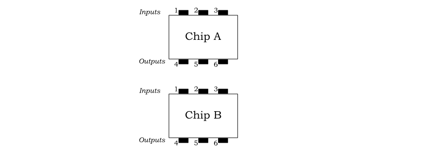
Boundary scan testing is a way of testing that the inputs and outputs of components on a board, or sub-systems on a chip, are connected correctly.
Figure 2.1 shows a board with two chips, A and B, each with three inputs (numbered 1 to 3) and three outputs (numbered 4 to 6).
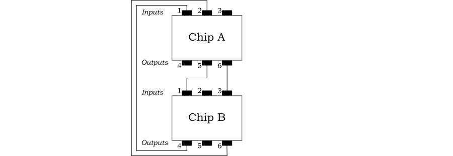
These chips are interconnected as shown in Figure 2.2. Output pins 5 and 6 of chip A are connected to the input pins 1 and 3 of chip B respectively. Output pins 4 and 6 of chip B are connected to input pins 1 and 2 of chip A respectively. The other pins are not connected.
The objective of boundary scanning is to determine that the inputs and outputs which should be connected, are connected, and that those which should not be connected are not connected.
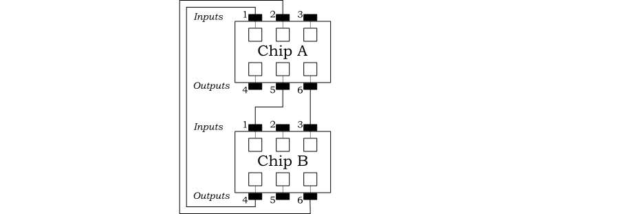
Boundary scan adds a simple logic cell (a scan cell) to each input and output, which can record the current state of that input or output as shown in Figure 2.3.
Normally the cell has no impact on the input or output. However the cells may be directed to capture the current state of the input or output. For inputs, the signal about to leave the chip is captured in the cell. For outputs, the signal about to enter the chip is captured in the cell.
The cells may also be directed to update their associated input or output. For inputs the stored value is injected onto the external connection. For outputs the stored value is injected into the chip.
![[Note]](./images/note.png) | Note |
|---|---|
There is a single signal controlling all the cells. So they will all capture or update their associated value at the same time. |
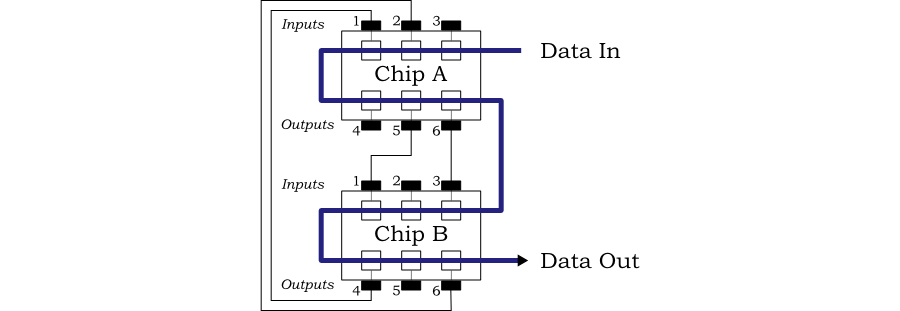
The final component of boundary scan is to connect all the scan cells together in a chain, so that each cell can transfer its value to the adjacent cell. This is shown in Figure 2.4.
The connected cells form a large shift register, with one bit for each input and output. The cells may be directed to shift their value to the adjacent cell. A sequence of shifts allows all the cells to be changed and all their values to be read out.
In the example shown, the cells form a 12-bit shift register, as shown in Figure 2.5.
A sequence of capture, followed by twelve shifts and then update allows the current state of each input to be recorded externally, a new set of values to be set and then injected onto the connections. In this way each input can be tested to check that when it is changed, its connected output changes.
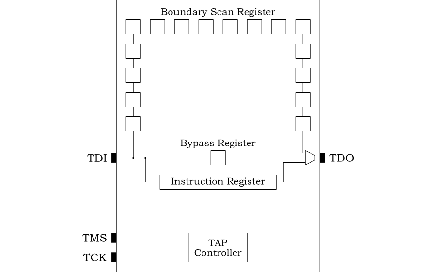
IEEE 1149.1 describes a simple architecture for chips implementing
boundary scan testing. In its minimal configuration, it provides
four external pins, a clock (TCK), data in (TDI), data out
(TDO) and a management signal (TMS). Collectively these pins are
known as the Test Access Port (TAP).
Internally there are two registers in addition to the boundary scan register: the instruction register and the bypass register. Figure 2.6 shows this minimal architecture.
Bits are shifted in on the positive edge of TCK and shifted out on
the negative edge. The TMS signal is used to control the register
into which the bits are shifted (instruction register, bypass
register or boundary scan register). TMS usage is described more
fully below.
The basic cycle of operation is a sequence of
capture a register, shift
in a new value from TDI, while simultaneously shifting out the old
value on TDO, then update the register with the
value shifted in.
The TAP controller can shift values either through the instruction register or through one of the other registers (collectively known as data registers). In the minimal configuration there are only two data registers: the boundary scan register and the bypass register. The bypass register is a convenient mechanism when boundary scan testing is not being used.
The instruction register must be at least 2 bits long. IEEE 1149.1 requires a minimum of 4 instructions:
BYPASSCapture, shift and update data through the bypass entry. This allows the chip to continue its normal operation. IEEE 1149.1 requires this instruction to consist of all 1's.
SAMPLECapture and shift data through the boundary scan register, thus taking a sample of the data entering and leaving the chip via its inputs and outputs. However the update phase does not drive data onto inputs or outputs.
PRELOADShift data through the boundary scan register, thus setting up a value in the scan cells for future use. For this instruction, the capture phase does not get the previous value into the cell and the update phase does not drive data onto inputs or outputs.
In early versions of the standard, this instruction was
combined with SAMPLE.
EXTESTThe chip is placed in extest mode before data is captured, shifted and updated through the boundary scan register.
This is used to test connectivity between multiple chips. In
extest mode the chip does not try to
drive outputs or accept inputs. It is normal to use
PRELOAD to set up the boundary scan
register prior to EXTEST.
Early versions of IEEE 1149.1 required this instruction to consist of all 0's, although this is not the case in more recent versions.
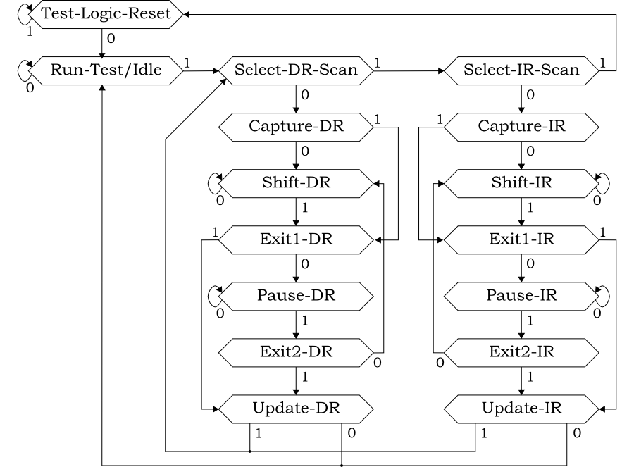
The TCK and TMS signals drive a finite state machine in the TAP
controller. TMS is sampled on the rising edge of TCK and used to
advance the state. The state machine is shown in Figure 2.7.
The actions taken in each state are as follows:
In this state all test-modes (for example extest-mode) are reset, which will disable their operation, allowing the chip to follow its normal operation.
At start-up the external logic will drive TMS high for at
least 5 TCK cycles. This guarantees to reach the
Test-Logic-Reset state and remain there.
This is the resting state during normal operation.
These are the starting states respectively for accessing one of the data registers (the boundary-scan or bypass register in the minimal configuration) or the instruction register.
These capture the current value of one of the data registers or the instruction register respectively into the scan cells.
This is a slight misnomer for the instruction register, since it is usual to capture status information, rather than the actual instruction with Capture-IR.
Shift a bit in from TDI (on the rising edge of TCK) and out
onto TDO (on the falling edge of TCK) from the currently
selected data or instruction register respectively.
These are the exit states for the corresponding shift state. From here the state machine can either enter a pause state or enter the update state.
Pause in shifting data into the data or instruction
register. This allows for example test equipment supplying
TDO to reload buffers etc.
These are the exit states for the corresponding pause state. From here the state machine can either resume shifting or enter the update state.
The value shifted into the scan cells during the previous states is driven into the chip (from inputs) or onto the interconnect (for outputs).
So we have a simple state machine, which allows either data registers or the instruction register to go through its capture-shift-update cycle, with an option to pause during the shifting.
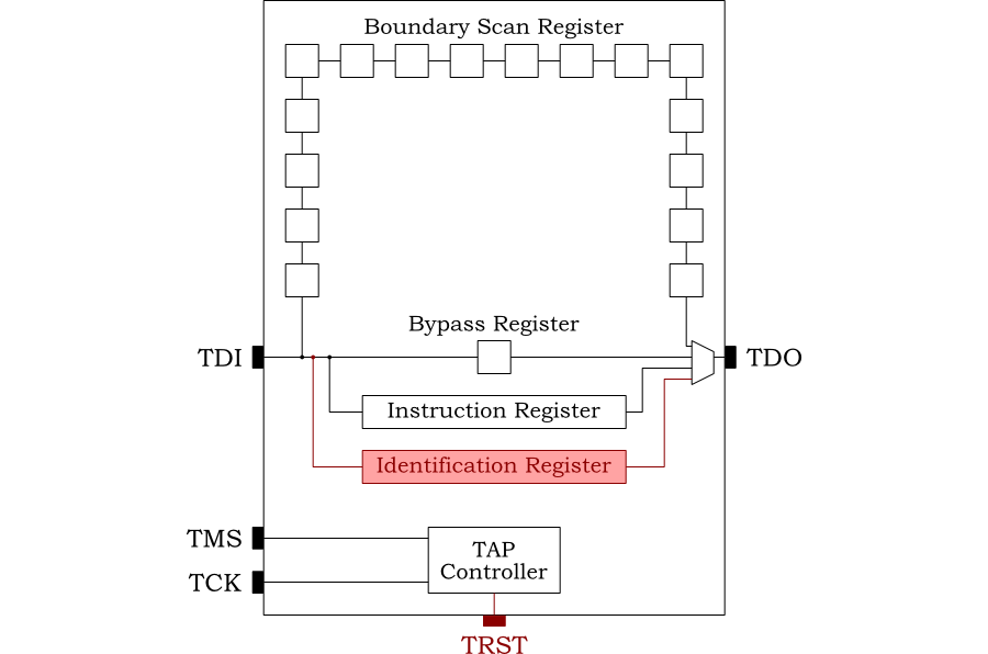
IEEE 1149.1 specifies an optional asynchronous reset pin, TRST,
an optional identification register and a number of optional
instructions that may be included. The extended architecture is
shown in Figure 2.8.
The reset pin, TRST, is active low. If driven low it immediately
takes the state machine to the Test-Logic-Reset state.
| Note |
|---|---|
If |
The device identification register is a
32-bit data register. It identifies version and part number for
both manufacture and user. It can be read using the optional
ICODE and USERCODE
instructions.
Additional instructions also support INTEST
(like EXTEST, but with on-chip test data),
RUNBIST (to run comprehensive
Built-in Self Test logic),
CLAMP (to clamp outputs to predefined logic
levels) and HIGHZ (to set all outputs to the
disabled (high impedance) state).
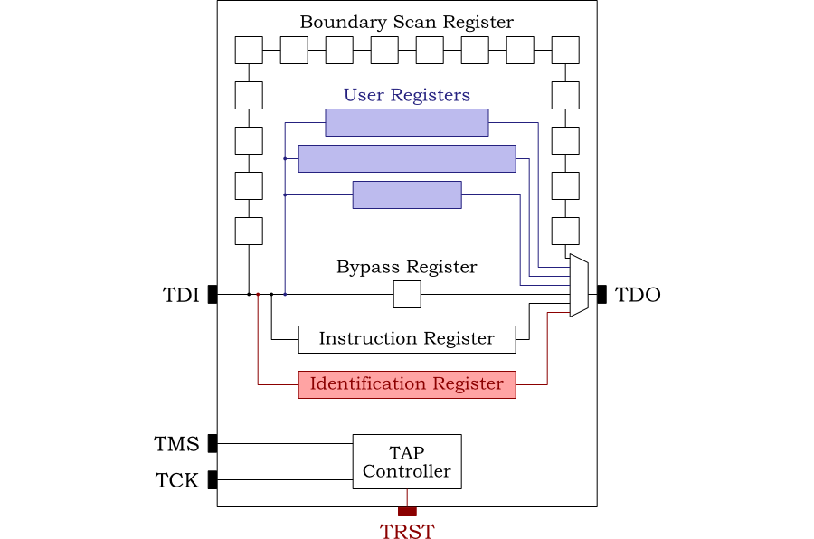
JTAG provides a generic mechanism for accessing registers on chip. The standard allows the architecture to be extended with user registers, accessed using the user's own instructions. Figure 2.9 shows how these registers may be added.
The user will add their own instructions to access these additional registers. This is a common mechanism to interface to debug units on modern system-on-chip (SoC) designs.
The development of SystemC as a standard for modeling hardware started in 1996. Version 2.0 of the proposed standard was released by the Open SystemC Initiative (OSCI) in 2002. In 2006, SystemC became IEEE standard 1666-2005 [5].
Most software languages are not particularly suited to modeling hardware systems[1]. SystemC was developed to provide features that facilitate hardware modeling, particularly the parallelism of hardware, in a mainstream programming language.
An important objective was that software engineers should be comfortable with using SystemC, even though it is a hardware modeling language. Rather than invent a new language, SystemC is based on the existing C++ language. SystemC is a true super-set of C++, so any C++ program is automatically a valid SystemC program.
SystemC uses the template, macro and library features of C++ to extend the language. The key features it provides are:
A C++ class, sc_module, suitable for
defining hardware modules containing parallel
processes.
| Note |
|---|---|
Process is a general term in SystemC to describe the various ways of representing parallel flows of control. It has nothing to do with processes in the Linux or Microsoft Windows operating systems. |
A mechanism to define functions modeling the parallel
threads of control within sc_module
classes;
Two classes, sc_port and
sc_export to represent points of
connection to and from a sc_module;
A class, sc_interface to describe the
software services required by a sc_port
or provided by a sc_export;
A class, sc_prim_channel to represent the
channel connecting ports;
A set of derived classes, of
sc_prim_channel,
sc_interface,
sc_port and
sc_export to represent and connect common
channel types used in hardware design such as signals, buffers and
FIFOs; and
A comprehensive set of types to represent data in both 2-state and 4-state logic.
The full specification is 441 pages long [5]. The OSCI reference distribution includes a very useful introductory user guide and tutorial [7].
[1] There are some exceptions, most notably Simula67, one of the languages which inspired C++. In some respects it is remarkably like SystemC.
This interface is designed for modeling environments which are both cycle accurate and pin accurate. In other words the state of each JTAG TAP port is accurately modeled on each bus cycle.
The objective is to provide a level of abstraction, so the user can concentrate on the modeling of register access through JTAG, rather than the minutiae of the TAP state machine and TAP signal states
JTAG offers fundamentally two operations: scan bits through the instruction register or scan bits through a data register. The only other operation required is the ability to reset the TAP controller.
The SystemC interface reflects this, with classes representing a TAP
instruction register scan (TapActionScanIR), a
TAP data register scan (TapActionScanDR) and
reset (TapActionReset).
The interface provides a SystemC module class representing the
JTAG interface, JtagSC. The user can queue IR
scan, DR scan and reset operations and JtagSC
will generate the correct sequence of TAP pin outputs.
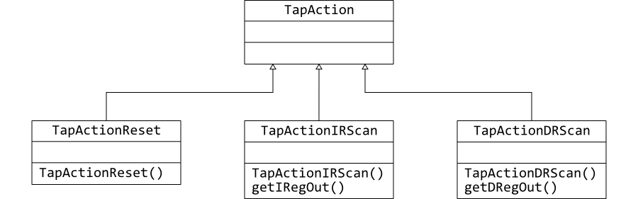
TAP actions are represented by the abstract C++ class,
TapAction. The three specific actions for
reset, scan IR and scan DR are sub-classed from this. Figure 3.1 shows this relationship and
summarizes the public interface as a class diagram.
This class represents a reset action for the TAP controller. There are no publicly accessible member variables of this class. The public methods are:
TapActionReset (sc_core::sc_event *_doneEvent)
The constructor for new TAP reset actions. It is passed a
pointer to a SystemC event in _doneEvent,
which will be notified when the action is complete.
This class represents the action of scanning a value through the instruction register. There are no publicly accessible member variables of this class. The public methods are:
TapActionIRScan (sc_core::sc_event *_doneEvent,
                 uint32_t           _iRegIn,
                 int                _iRegSize)
The constructor for new TAP IR scan actions. It is passed
a pointer to a SystemC event in
_doneEvent, which will be notified when
the action is complete.
The value to be scanned in (which will form the sequence of
bits on TDI) is represented as a 32-bit integer in
iRegIn. The actual number of bits to be
scanned is an integer in _iRegSize.
32-bits seems a reasonable limit for the size of instruction register in any realistic JTAG architecture.
uint32_t getIRegOut ();
On completion of the action (as signaled through the
SystemC event pointed to by _doneEvent
this method will return the information that was scanned out
of the instruction register. That is the sequence of bits
that have appeared on TDO
As noted above, in the case of the instruction register this is not the actual value of the instruction, but some status bits about the interface.
This class represents the action of scanning a value through a data register. This is more complex, because data registers are potentially very large—often larger than the 64-bits the largest integer that can be held in a single C++ variable.
To support this, values are represented as an array of 64-bit unsigned integers (uint64_t). However, for efficient handling of smaller data registers, variants are provided which represent the register in a single 64-bit uint64_t.
There are no publicly accessible member variables of this class. The public methods are:
TapActionDRScan (sc_core::sc_event *_doneEvent,
                 uint64_t           _dRegInArray[],
                 int                _dRegSize)
The constructor for new DR scan actions. It is passed a
SystemC event in _doneEvent, which will
be notified when the action is complete.
The value to be scanned in (which will form the sequence of
bits on TDI) is represented as an array of 64-bit unsigned
integers in dRegInArray. The actual
number of bits to be scanned is an integer in
_dRegSize.
This interface allows data registers of any size to be handled. However if this constructor is used for a small value it will automatically use the more efficient constructor described next.
TapActionDRScan (sc_core::sc_event *_doneEvent,
                 uint64_t           _dRegIn,
                 int                _dRegSize)
An alternative constructor for smaller registers (up to 64-bits). This is for use where the data to be scanned in is up to 64-bits long. It can be used for larger registers, so long as the actual value to be scanned in is only 64 bits or fewer.
The constructor is passed a SystemC event in
_doneEvent, which will be notified when
the action is complete.
The value to be scanned in (which will form the sequence of
bits on TDI) is supplied as a 64-bit unsigned integer in
dRegIn. The actual number of bits to be
scanned is an integer in _dRegSize.
~TapActionDRScan ()
The destructor for DR scan actions. When handling more than 64 bits, arrays are allocated for internal data. If such arrays have been created, the destructor deletes them.
void getDRegOut (uint64_t dRegArray[])
On completion of the action (as signaled through the
SystemC event pointed to by _doneEvent
this method will return the information that was scanned out
of the instruction register. That is, the sequence of bits
that have appeared on TDO
The result is copied into the uint64_t array
supplied in dRegArray. This interface can
be used, even if this is a small register that can be held
in a single variable. The result will be copied into
dRegArray[0].
uint64_t getDRegOut ();
On completion of the action (as signaled through the
SystemC event pointed to by _doneEvent
this method will return the information that was scanned out
of the instruction register. That is, the sequence of bits
that have appeared on TDO.
The value returned can be no larger than 64-bits. However this call may be used with a larger data register, in which case it will return the least significant 64 bits.
This SystemC module class provides the primary interface. Users can
queue instances of TapAction on its FIFO and
it will generate the correct sequence of JTAG tap pin signals.
JtasSC defines a set of signal ports to
connect to the target model implementing JTAG
sc_core::sc_in<bool> sysReset
Input. The system wide reset signal (active
high). Whenever this is active JtagSC will
drive the TRST signal to its active state (low).
sc_core::sc_in<bool> tck
Input. The JTAG clock signal. This must be
synchronous with the TCK signals to connected devices
implementing JTAG
sc_core::sc_out<bool> tdi
Output. The TDI signal. For
JtagSC it is an
output, because this class is generating
the required signals on TDI from the actions which have been
queued.
sc_core::sc_in<bool> tdo
Input. The TDO signal. For
JtagSC it is an
output from which the result of the actions
which have been queued is built up
sc_core::sc_out<bool> tms
Output. The TMS signal. For
JtagSC it is an
output, because this class is generating
the required signals to drive the TAP state machine from the
actions which have been queued.
sc_core::sc_out<bool> trst
Output. The TRST signal. Driven low
(active) whenever the system reset (sysReset)
is active (high). For JtagSC it is an
output, because this class generates the
reset when required.
Users connecting to modules which do not implement TRST should
tie this off to a dummy signal
JtasSC defines a FIFO on which users queue
JTAG actions.
sc_core::sc_fifo<TapAction *> *tapActionQueue
The JTAG actions are of type TapAction
and its subclasses. Over successive TCK cycles, the
JtagSC will generate the required TMS and
TDI signals and capture the TDO signals. When complete the
SystemC sc_event from the action's
creation is signaled.
The public methods of JtagSC are:
JtagSC (sc_core::sc_module_name  name,
        int                      fifo_size = DEFAULT_TAP_FIFO_SIZE)
The constructor of new JTAG modules. The first argument,
name, like all SystemC modules, is the name
of the module. The optional second argument specifies the size
of FIFO on which actions may be queued. Its default value,
DEFAULT_TAP_FIFO_SIZE is 256 in the current
implementation.
~JtagSC ()
The destructor for JTAG modules. This deletes the FIFO and a number of internal data structures.
The user should instantiate an instance of
JtagSC for each JTAG interface on the
target model. The JtagSC ports should be
connected to the system reset and TAP signal ports on the model
using SystemC signals of type
sc_signal<bool>.
Other SystemC modules may then queue actions by writing instances of
TapActionReset,
TapActionIRScan and
TapActionDRScan to the
JtagSC FIFO. This is normally within the
context of a SC_THREAD, allowing the module to
wait for notification when each action is
complete.
The current implementation has been verified under Fedora 9 Linux using OSCI SystemC 2.2 and GCC 4.3.0. The author welcomes feedback about use under other operating systems.
Unpack the source file, and change to the directory where the source is unpacked.
jxf embecosm-esp4-sysc-jtag-ca-1.0.tar.bz2
cd embecosm-esp4-sysc-jtag-ca-1.0
Ensure the environment variable SYSTEMC is set to
point to your SystemC distribution.
Build the cycle accurate SystemC JTAG library.
make
In the current implementation, there is no
make install. Copy the resulting
libjtagsc.a library and
jtagsc.h header to the library and header
directories of choice if desired.
To use the library, add the header directory to the GCC preprocessor flags and the library directory and library to the final linking command line. For example.
gcc -Iembecosm-esp4-sysc-jtag-ca-1.0 testprog.cpp
gdd -Lembecosm-esp4-sysc-jtag-ca-1.0 testprog.o -ljtagsc -o testprog
Each class described in the API is implemented as a header file
defining the class and a code file with implementation of all the
methods. So the class JtagSC is defined in
JtagSC.h and implemented in
JtagSC.cpp.
In addition to the classes described in Section 3.2,
there is one more class, TapStateMachine,
implementing the behavior of the TAP state machine.
The following sections provide brief notes on the implementation of each class.
In addition to the public instance variables which form part of the API, the main JTAG module maintains some private state.
TapStateMachine *stateMachine
This is an instance of the TAP state machine class (see Section 3.4.6), modeling the TAP state machine in the target to which this module is connected.
TapAction *currentTapAction
This is the JTAG action currently being processed through the TAP state machine. It has already been read from the FIFO.
The constructor initializes the current TAP action
(currentTapAction) to NULL
and allocates new instances of the FIFO
(sc_fifo) and the TAP state machine
(TapStateMachine).
It also declares the protected method
processActions to be a SystemC method
(SC_METHOD), sensitive to the rising TCK
(tck.pos()). It is this method that is
responsible for progressing the queued actions on each clock
cycle.
The destructor deletes the FIFO and TAP state machine to free the memory on completion.
This function is declared in the constructor as a SystemC
SC_METHOD. It is invoked on every rising edge
of TCK.
TRST takes its value as the inverse of the System reset (since it
is active low, while the latter is active high). If the system is
in reset, there is nothing else to do and the method returns.
If there is no TAP action currently being processed
(i.e. currentTapAction is
NULL) then the method attempts a non-blocking
read from the FIFO.
If no new action is available from the FIFO, then TMS is driven to
the appropriate state to move towards the Run-Test/Idle
state and the method returns.
Having obtained (or already in progress of) a TAP action, its
process method is invoked. This takes the
current state machine and TDO and returns (via parameters) new
values of TDI and TMS. It returns success if this completes the
action.
In the event of successful completion, the SystemC event
associated with the action is notified, and
currentTapAction marked null, so a new action
will be obtained from the FIFO on the next cycle.
The state machine is then advanced to its next state (based on the
value of TMS), and the values of TMS and TDI used to drive the
SystemC signals in tdi_o and
tms_o.
| Note |
|---|---|
This function is only called on the positive edge of the clock,
although |
This is the abstract base class of all the TAP action classes. It
provides the common interface, expected by
JtagSC.
JtagSC is declared a
friend class and the pure virtual
process method is made protected. This method
can therefore be called by JtagSC, but not by
other users of the class. Subclasses of
TapAction are expected to implement this
method.
Although there are no public instance variables which form part of the
API, TapAction maintains some private state.
sc_core::sc_event *doneEvent
The SystemC event which will be notified when an action completes.
int resetCounter
A counter for use when resetting the TAP state machine of the
target through checkResetDone (see below).
In addition to the pure virtual process method,
TapAction provides the function
checkResetDone (see below) as a utility for its
subclasses.
The TapActionIRScan and
TapActionDRScan subclasses rely on the
TAP state machine in JtagSC being an
accurate reflection of the TAP state machine in the target. This
can only be the case if both have been through a synchronous reset
cycle (5 or more TMS=1 cycles).
The TRST signal cannot be used as a guide, since it is an optional
signal, which may not be implemented by targets.
Instead the TAP state machine class,
TapStateMachine records whether it has been
through a reset cycle. It relies on other classes to use (and set)
this information as is helpful.
Both TapActionIRScan and
TapActionDRScan check this information, and
if necessary force the state machine through a reset to
synchronize with the model.
This method is a utility to provide that function for
subclasses. A subtlety of its implementation is that it sets the
value of the TAP state machine flag as soon as it has provided
the final (fifth) TMS signal, but does not return
true to indicate no reset is needed until its
subsequent call. This allows users to distinguish whether they are
about to complete reset, or have already completed it in the
previous TCK cycle. This in turn allows the method to provide the
functionality for TapActionReset.
This is the simplest of the TapAction
subclasses, implementing a JTAG reset cycle. It has a sole private
instance variable.
bool firstTime
This is used to track the first call of the
process method.
On the first cycle through, the TAP state machine's
resetDone flag is cleared.
This allows the base class checkResetDone
method to be used to drive the reset.
In this case completion is when the TAP state machine records
the reset is done, not when the
checkResetDone function returns
true. This means completion is signaled on
the final reset cycle, rather than after the final reset
cycle. See Section 3.4.2 for the
explanation of this behavior.
This class implements capture, shift and update of a value through the instruction register. It has a number of private instance variables.
uint32_t iRegIn
This is the value being shifted in through TDI. It holds the
remaining bits to be shifted.
int iRegSize
This is the number of bits to be shifted in through TDI and out
through TDO
uint32_t iRegOut
This is the value being shifted out through TDO. It holds the
bits shifted out so far.
int bitsShifted
The number of bits shifted in so far.
enum {
    SHIFT_IR_PREPARING,
    SHIFT_IR_SHIFTING,
    SHIFT_IR_UPDATING
  } iRScanState
This enumeration records where the action is in its process. The
process method follows a state machine (see
below) whose state is recorded here.
The primary responsibility of the constructor is to initialize all
the instance variables. The input register and size are taken from
the arguments, the output register and count of bits shifted are
zeroed and the IR-Scan process state machine is set to
SHIFT_IR_PREPARING.
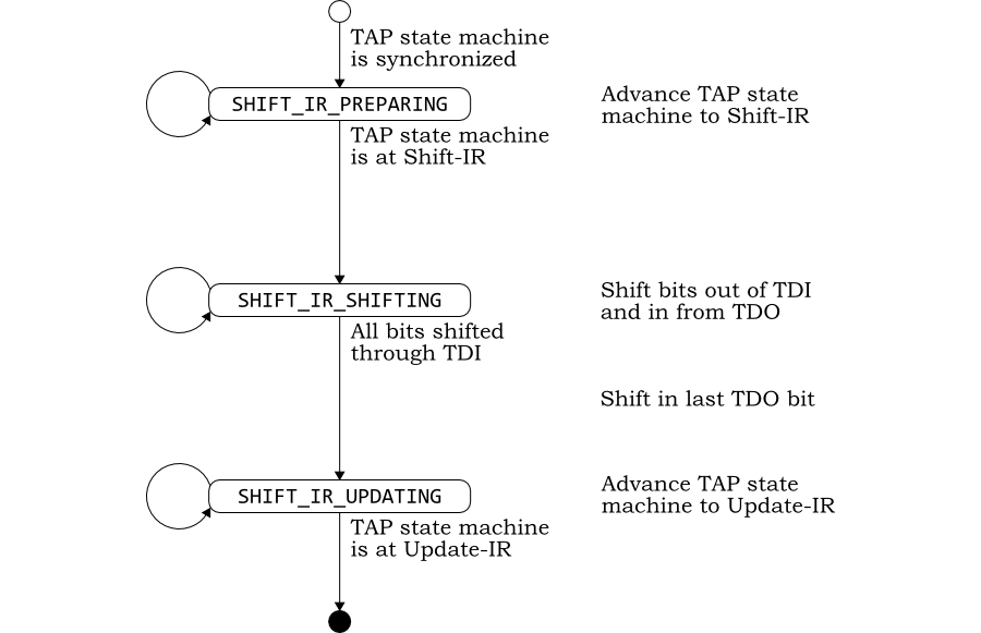
This method generates the appropriate values of TDI and TMS to
process the action and capture TDI. It is controlled by its own
state machine, whose state is recorded in
iRScanState as shown in Figure 3.2
A subtlety of the implementation is that, because TDO changes on
the falling edge, its value is always one
step later than that of TDI. Thus TDO is not captured on the first
cycle in Shift-IR state and its last bit is captured immediately
after leaving Shift-IR state.
This class implements capture, shift and update of a value through a
data register. Functionally it is very similar to
TapActionIRScan. However complexity is added,
because data registers may be too large for a single C++ variable,
so must be represented in
arrays. TapActionDRScan has a number of
private instance variables.
int dRegBitSize
This is the number of bits to be shifted in through TDI and out
through TDO.
int dRegWordSize
If dRegBitSize is more than 64, this is the
number of elements in the uint64_t array used to
represent the input and output registers, with the least
significant bits in element 0.
uint64_t topMask
If register values are held in an array
(i.e. dRegBitSize is more than 64), any odd
number of bits (if dRegBitSize is not an
exact multiple of 64) are held in the most significant element
of the array. This is a mask for those bits.
uint64_t *dRegInArray
When the registers are held in an array
(i.e. dRegBitSize is more than 64), this is a
pointer to the array representing the value being shifted in
through TDI. It holds the remaining bits to be shifted.
Since the original value is destroyed during processing, this is a copy of the array supplying the original value to the constructor.
uint64_t dRegIn
If the number of bits in a register (held in
dRegBitSize) is 64 or less, the value to be
shifted through TDI can be held in this simple variable for
efficiency.
uint64_t *dRegOutArray
When the registers are held in an array
(i.e. dRegBitSize is more than 64), this is a
pointer to the array representing the value being shifted out
through TDO. It holds the bits shifted out so far.
uint64_t dRegOut
If the number of bits in a register (held in
dRegBitSize) is 64 or less, the value being
shifted out through TDO can be held in this simple variable for
efficiency.
int bitsShifted
The number of bits shifted in so far.
enum {
  SHIFT_DR_PREPARING,
  SHIFT_DR_SHIFTING,
  SHIFT_DR_UPDATING
} dRScanState
This enumeration records where the action is in its process. The
process method follows a state machine (see
below) whose state is recorded here.
As with the instruction register, the primary responsibility of
the constructor is to initialize all
the instance variables. The register size is taken from
the arguments, the count of bits shifted is
zeroed and the DR-Scan process state machine is set to
SHIFT_DR_PREPARING.
There are two variants depending on whether the value to be
shifted in through TDO is small enough to fit in a single 64-bit
variable.
In either case, if the number of bits in the register size is greater than 64, the registers will be represented as an array of uint64_t. Otherwise they will be represented as simple uint64_t variables for efficiency.
Where registers are represented as vectors, new vectors of the
correct size are allocated and the supplied input value copied
to the input register. The output register is zeroed. The size of
the vectors is recorded in dRegWordSize.
Otherwise the input value is copied to the local instance variable
(dRegIn) and the output value
(dRegOut) is zeroed.
The destructor is used to delete the local copies of registers where they have been represented as arrays to free the memory.
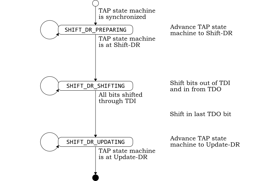
As with TapActionIRScan, this method
generates the appropriate values of TDI and TMS to process the
action and capture TDI. It is controlled by its own state machine,
whose state is recorded in iRScanState as shown
in Figure 3.3
The operations on the registers vary depending on whether the
register is more than 64 bits long. These operations (to shift
bits out for TDI and in from TDO) are placed in separate
utility functions, shiftDRegOut and
shiftDRegIn (see below).
This function is part of the public API, allowing the user to
access the value shifted through TDO on completion.
It is provided in two versions. In the first, the result is copied to an array of uint64_t provided as an argument. This version may be used even if the register is 64 bits or smaller. The value will be copied into element 0 of the array.
The second version returns the value as a uint64_t. This version may be used, even if the register is more than 64 bits long. The least significant 64 bits will be returned.
These functions are used to shift the least significant bit out of
dRegInArray (for use as TDI) and the shift in
the most significant bit (from TDO) of
dRegOutArray. However if the data register is
represented as a scalar uint64_t variable they will
perform the equivalent operation on DRegIn and
DRegOut instead.
This class is for internal use by JtagSC and
the various TAP action classes. It maintains the interface's model
of the state machine in the TAP Controller.
The header defining this class also defines
enum TapState for the various states of
the TAP state machine.
TapStateMachine has a number of private
instance variables.
TapState state
The current state.
bool resetDone
The TAP state machine is only of use if it correctly reflects
the state machine in the TAP Controller of the target. This
flag may be set and read by users to reflect whether the two are
in synchrony (for example having gone through a sequence of 5 or
more TMS=1 transitions).
The constructor initializes the state to Test-Logic-Reset and clears the flag indicating the TAP controller has been reset. Until a reset has been completed, there can be no confidence that the state is a correct reflection of reality.
The functions getState is provided to get the
current state. The functions getResetDone and
setResetDone are provided to access the flag
indicating whether a reset has been completed. Although
initialized to false, it is the responsibility of users to set
this flag to its correct value.
This function returns through its second argument a value of TMS
which will move from the current state to the specified target
state most efficiently (i.e. smallest number of steps). Table
lookup makes this an efficient function.
The return value indicates if the state machine was already in the target state.
This function is used by the instruction and data scan TAP
action classes to get to the correct state during their
process functions.
Both examples in this chapter use the OpenRISC Reference Platform System-on-Chip, ORPSoC ([6]). A cycle accurate SystemC model was generated automatically from the source using Verilator ([8]).
ORPSoC features a JTAG interface with a number of user register which drive its debug unit. These examples show the result of resetting the unit, writing a register less than 64-bits long and reading a register more than 64-bits long.
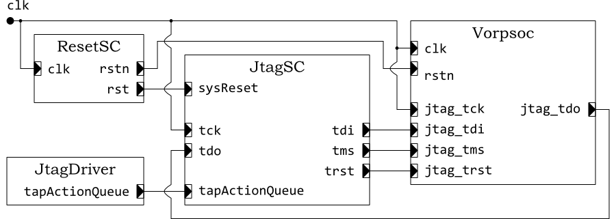
The SystemC model consists of four modules: the ORPSoC module created
by Verilator (class Vorpsoc), a reset signal
generator (class ResetSC), the JTAG module
using the interface described in this application note (class
jtagSC) and a simple driver module to inject
JTAG requests (class JtagDriver). The module
structure and their interconnects are shown in Figure 4.1.
The clock is provided by a sc_clock and used to
drive both the system clock of ORPSoC and the JTAG TCK signals. The
reset generator, ResetSC generates a reset signal
for a predefined number of clock cycles after time zero. The two outputs
offer active high (rst) and active low
(rstn) versions, synchronous with each other.
The code to drive reset of the JTAG is as follows.
sc_core::sc_event *actionDone = new sc_core::sc_event();
TapActionReset    *resetAction;

resetAction = new TapActionReset (actionDone);
tapActionQueue->write (resetAction);
wait (*actionDone);

delete resetAction;
delete actionDone;
A new instance of TapActionReset,
resetAction is created using the SystemC event,
actionDone. This action is queued by writing to the
FIFO (tapActionQueue, waiting for the result on
actionDone.
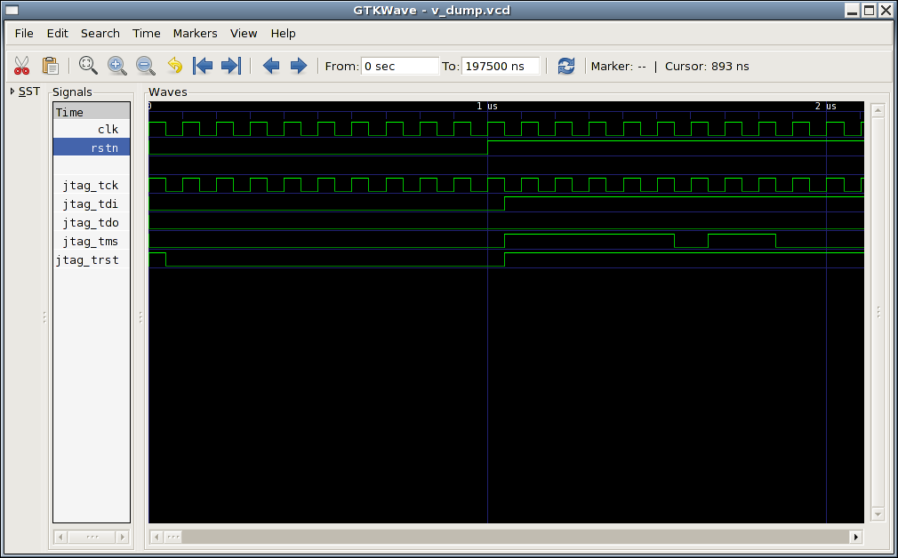
With the results traced in a VCD the effect can be seen clearly. The trace is shown in Figure 4.2.
During system reset, the JTAG TRST is driven low. As soon as the
system reset is complete at 1μs, the JTAG reset can be
processed. A sequence of 5 cycles of TMS=1 is seen from 1μs
onwards.
| Note |
|---|---|
The VCD trace shows the signals changing on the falling edge of the clock. This is a cycle accurate model, with values only sampled on clock edges. The JTAG signals change in response to the stimulus from the clock, so only appear in the trace at the next clock edge. This is a common effect in cycle accurate modeling, but does not affect the behavior of the model. |
The ORPSoC JTAG interface uses a 4-bit instruction register with a
number of custom instructions. One such instruction
CHAIN is used to select the custom CHAIN
register. This instruction has the binary value 0011.
The code to write the CHAIN instruction into the
instruction register is:
sc_core::sc_event *actionDone = new sc_core::sc_event();
TapActionIRScan   *iRScan;

iRScan = new TapActionIRScan (actionDone, CHAIN_SELECT_IR, JTAG_IR_LEN);
tapActionQueue->write (iRScan);
wait (*actionDone);

delete iRScan;
The action is created as a new instance of
TapActionIRScan, passing in a SystemC event
for signaling completion, with the value of the instruction
(CHAIN_SELECT_IR, binary 0011) and the instruction
register length (JTAG_IR_LEN, 4 in the case of
ORPSoC).
| Note |
|---|---|
In this case the SystemC event, |
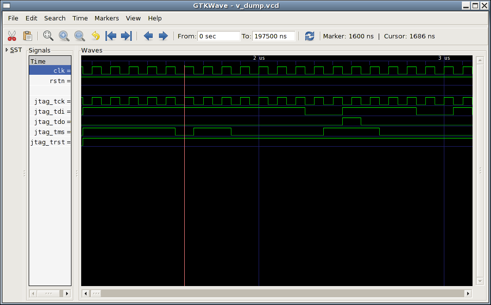
The results are again traced in a VCD and shown in Figure 4.3.
The instruction register write action commences at 1.6μs. A
sequence of 0-1-1-0-0 on TMS takes the state machine from its starting
point of Test-Logic-Reset through Run-Test/Idle, Select-DR-Scan,
Select-IR-Scan and Capture-IR to Shift-IR.
At this point a sequence of four TMS=0, starting at 2.0μs allow the
bits of the instruction register to be shifted in from TDI. The
sequence 1-1-0-0 can be seen on jtag_tdi. Since the
bits are shifted in least-significant bit first, this represents the
binary number 0011, the CHAIN instruction.
A sequence of 1-1 on TMS moves the state machine through Exit1-IR to
Update-IR at which point completion is signaled (2.5μs).
The ORPSoC JTAG CHAIN instruction selects the
debug unit's 12-bit CHAIN register as the data register to be written.
The code to write the data into the CHAIN data register is:
uint64_t  dReg = 0x4;
dReg |= crc8 (chain, 4) << 4;

dRScan = new TapActionDRScan (actionDone, dReg, 12);
tapActionQueue->write (dRScan);
wait (*actionDone);

delete dRScan;
delete actionDone;
The 12-bit data is built up in dReg from a value
(bits 0-3) and a CRC (bits 4-11). The action is created as a new
instance of TapActionDRScan, passing in a
SystemC event for signaling completion (reusing the signal from the
instruction register write earlier), with the data value and the data
register length. In this example the 12-bit value is 0000_1110_0100.
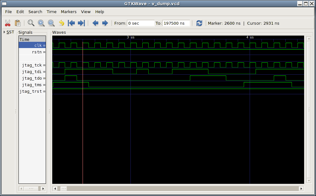
The results are again traced in a VCD and shown in Figure 4.4.
The data register write action commences at 2.6μs. The TAP state
machine is currently at Update-IR from the previous write of an
instruction register. A TMS sequence of 1-0-0 takes the state through
Select-DR-Scan and Capture-DR to Shift-DR. 12 cycles in Shift-DR (the
last with TMS=1 to move out of Shift-DR) starting at 2.9μs shift in
the sequence 0-0-1-0-0-1-1-1-0-0-0-0 on TDI, the value specified,
least significant bit first. The final TMS=1 moves the state to
Exit1-DR, followed by another TMS=1 to move to Update-DR. Completion
can be signaled at this point, at time 4.1μs.
In this example the bits being shifted out on TDO can also be
seen. The ORPSoC debug unit always shifts out the CRC as the last
8-bits, and the sequence 0-1-1-1-0-0-0-0 can be seen as the final bits
on TDO, which is the original 8-bit CRC (00001110) in least
significant bit first.
Note how the bits are delayed half a cycle from the TDI bits, because
TDO changes on the falling edge of TCK (and on this cycle accurate
trace will be shown on the following rising edge). Thus the final bit
is picked up as the Exit1-DR state is entered.
This final example shows the JTAG interface's facilities for handling large data registers. This example shows a read from one of the ORPSoC JTAG 73-bit debug registers
The code to read a register also involves scanning in data, and for ORPSoC that data must have a correct CRC to be accepted. The code is as follows:
sc_core::sc_event *actionDone = new sc_core::sc_event();
uint64_t dRegArray[2];
memset (dRegArray, 0, 16);
dRegArray[0] |= data;
uint8_t crc_in = crc8 (dRegArray, 65);
insertBits (crc_in, 8, dRegArray, 65);

TapActionDRScan *dRScan = new TapActionDRScan (actionDone, dRegArray, 73);
tapActionQueue->write (dRScan);
wait (*actionDone);

dRScan->getDRegOut (dRegArray);
delete dRScan;
delete  actionDone;
The 73-bit data is built up in the array dRegArray
from a value (bits 0-64) and a CRC (bits 65-72). The action is created
as a new instance of TapActionDRScan, passing
in a SystemC event for signaling completion, with the data value
array and the data register length.
After completion, the result is retrieved back into dRegArray using
the getDRegOut method of the
TapActionDRScan class.
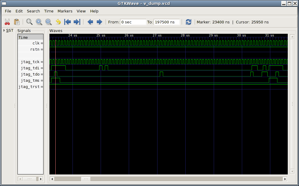
The results are again traced in a VCD and shown in Figure 4.5.
The data register read action commences at 23.4μs. The TAP state
machine is currently at Update-IR from the previous write of an
instruction register. A TMS sequence of 1-0-0 takes the state through
Select-DR-Scan and Capture-DR to Shift-DR. There are then 73 cycles in
Shift-DR (the last with TMS=1 to move out of Shift-DR) starting at
23.7μs. The value is shifted out least significant bit first on TDO
(one cycle delayed, since it is on the negative edge). The value is
0x0620000000200000000.
The final TMS=1 moves the state to Exit1-DR, followed by another TMS=1
to move to Update-DR. Completion can be signaled at this point, at
time 31.1μs.
This application note presents a SystemC interface suitable for cycle accurate modeling of JTAG. It will be of value to engineers developing cycle accurate models, who need to interface to other modules, to develop test benches, or to connect to tools such as debuggers.
Suggestions for corrections or improvements are welcomed. Please contact
the author at jeremy.bennett@embecosm.com.
Hardware logic model which is based only on logic high and logic low (binary 0 and binary 1) values.
See also 4-state.
Hardware logic model which considers unknown (X)
and unproven (Z) values as well as logic high and
logic low (binary 0 and binary 1).
See also 2-state.
A description of the relationship between byte and word addressing on a computer architecture. In a big endian architecture, the least significant byte in a data word resides at the highest byte address (of the bytes in the word) in memory.
The alternative is little endian addressing.
See also little endian.
JTAG is the usual name used for the IEEE 1149.1 standard entitled Standard Test Access Port and Boundary-Scan Architecture for test access ports used for testing printed circuit boards and chips using boundary scan.
This standard allows external reading of state within the board or chip. It is thus a natural mechanism for debuggers to connect to embedded systems.
A description of the relationship between byte and word addressing on a computer architecture. In a little endian architecture, the least significant byte in a data word resides at the lowest byte address (of the bytes in the word) in memory.
The alternative is big endian addressing.
See also big endian.
The industry standardization body for SystemC/
A silicon chip which includes one or more processor cores.
A set of libraries and macros, which extend the C++ programming language to facilitate modeling of hardware.
Standardized by the Open SystemC Initiative, who provide an open source reference implementation.
See also Open SystemC Initiative.
The interface to a JTAG interface defined by IEEE 1149.1.
[1] Doxygen: Source code documentation generator tool, Dimitri van Heesch, 2008 . http://www.doxygen.org
[2] Embecosm Software Package 4. Cycle Accurate SystemC JTAG Interface: Reference Implementation. Embecosm Limited, January 2009. Available for free download from the Embecosm website at www.embecosm.com .
[3] IEEE standard test access port and boundary-scan architecture IEEE Computer Society 2001 (reaffirmed 2008) . IEEE Std 1149.1™-2001 .
[4] IEEE Std 1149.1 (JTAG) Testability: Primer. Texas Instruments Semiconductor Group 1997. Available for free download from the Texas Instruments website at focus.ti.com/lit/an/ssya002d/ssya002d.pdf .
[5] IEEE Standard SystemC® Language: Reference Manual. IEEE Computer Society 2005 . IEEE Std 1666™-2005. Available for free download from standards.ieee.org/getieee/1666/index.html .
[6] The OpenRISC Reference Platform System-on-Chip ORSoC AB (through the OpenCores website) www.opencores.org
[8] Verilator 3.700. Wilson Snyder, January 2009. Veripool, www.veripool.org/wiki/verilator