I’m Mitchell and I spent two weeks on work experience with Embecosm. Before I came I had limited experience with electronics and next to no experience with programming, however, over the two weeks I’ve spent here my knowledge has vastly increased.
The Task
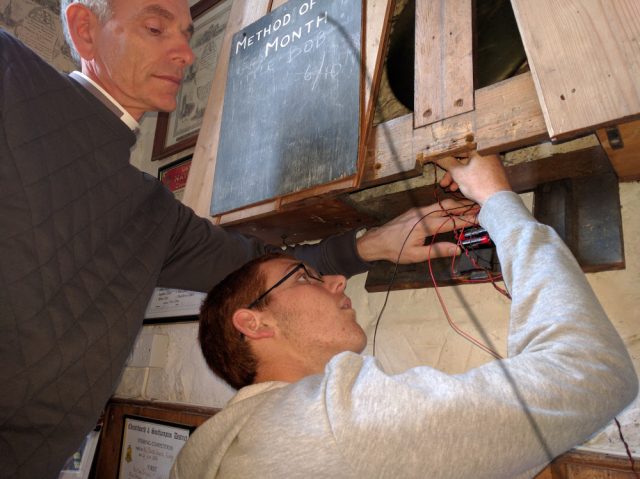
I was tasked with the challenge of timing the pendulum which drives the clock in St. Thomas church (Lymington) next door. I worked closely with the vicar, Peter Salisbury, who was a great help advising and guiding me throughout, as well as contributing lots of ideas and translating technical talk that I couldn’t make sense of. The clock was currently set using an atomic clock on a phone and this meant it had to be reset every week because it wasn’t accurate enough. The hope was that by the time I’d finished my two weeks, it would be accurate to within one second per week. The clock uses a four second pendulum, so this means that for every full swing the timing had to be accurate to within six millionths of a seconds — or six microseconds — which has proved challenging, frustrating and tedious, and also positively enjoyable.
Starting
I started by producing a simple ‘Shrimping Persistence of Vision‘ kit which blinked LED’s on and off to spell out a word. Building it didn’t prove too challenging, but getting the example program did, because the TinyURL in the instructions didn’t work. However, by lunch I was playing with the program and familiarizing myself with the software I’d be using for the next two weeks. After this I assembled the Cuttlefish board. Whilst the most difficult part of this was cutting the headers to the right length, it was considerably more time consuming and challenging than the Shrimping Persistence of Vision kit due to the soldering and increased number of parts. Despite this it worked fine when I finally had the resistor and LED which are used to test it in the correct place.
Choosing the Method
Most of my second day was spent researching different methods and sensors that could be used to time the pendulum. A book titled ‘Sensor kit for Arduino MAKE IT EASY MAKE IT FUN’ proved very useful for this. It listed thirty different Arduino sensors, which saved a lot time and effort researching. The main ideas included: using a Hall sensor to detect the magnetic field of the iron pendulum as it went past, a laser range finder, using the Doppler effect in some way, and using a microphone to time the tick of the clock was also suggested. However, these methods were deemed either unreliable, impractical, or expensive and the method that I eventually chose was a light gate using a photo-resistor and a laser. This was practical, simple (on paper at least) and cheap since I already all the required sensors, chips, wires, etc. close to hand.
Researching the Program
Throughout programming I have been using the Internet to find programs for timing and the sensor. These programs, eventually integrated with each other and ideas from various people, resulted in a long program that was functional but not entirely accurate. Originally when the sensor reading was above a certain level an LED shone and when it went below that level the LED turned off. After more research I found code which printed the time since the program started through Serial monitor. After considerable help I eventually integrated this into the LED program so that the time of each swing was displayed. It was decided at this point that an LCD display would be better than the Serial monitor, because it meant that the program could run off a battery without needing a computer present.
With the LCD selected and fitted I found a program to drive it on the Internet and integrated this into the program, to replace the Serial monitor. After a test on the real pendulum we discovered that it wasn’t very accurate.
I returned and spent the rest of the day creating a new more accurate program based on another failed program, the current (long) program and an example of a finite state machine. The following day we had a more accurate version of the original program. This program was then altered to show an average and after another test was proven be inaccurate. The program was then altered again to make it more accurate and to show how fast or slow the clock would be after 24 hours. This took a couple of days to complete and was only tested on the approximately two second card pendulum.
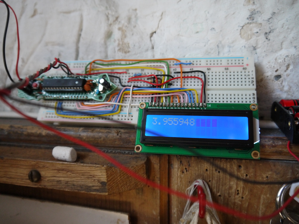
// Pendulum swing timer

// Copyright (C) 2017 Embecosm Limited <www.embecosm.com>

// Contributor: Mitchell

// This program is free software: you can redistribute it and/or modify
// it under the terms of the GNU General Public License as published by
// the Free Software Foundation, either version 3 of the License, or
// (at your option) any later version.

// This program is distributed in the hope that it will be useful,
// but WITHOUT ANY WARRANTY; without even the implied warranty of
// MERCHANTABILITY or FITNESS FOR A PARTICULAR PURPOSE.  See the
// GNU General Public License for more details.

// You should have received a copy of the GNU General Public License
// along with this program.  If not, see <http://www.gnu.org/licenses/>.


// All times are in whole numbers of microseconds, unless the variable has the suffix _secs,
// in which case the time is in seconds and is floating point.

#include <LiquidCrystal.h>

const unsigned CUTOFF = 115;                   // >= this value, sensor is off
const unsigned MAX_SWINGS = 200;                // Number of swings to average
const unsigned PRINT_FREQ = 10;                 // How often to print data
const double SWINGS_PER_DAY = 21600.0;          //number of swings of pendulum in 24 hours
const double SECS_PER_DAY = 86400.0;               //number of seconds in a day
const double CORRECTION_FACTOR = 4.0 / 3.956;      //to increase accuracy


LiquidCrystal lcd(12, 11, 10, 9, 8, 7, 6, 5, 4, 3, 2);     //select the pins for the lcd
int sensorPin = A0;                                        //select the input for the photoresistor
int ledPin = 1;

unsigned long prev_time;      // Start of previous swing

enum state {
  ON,
  OFF
};

enum state prev_state;       // Previous state of pendulum

int  change_count;           // Expect 4 changes per swing

int  next_res;               // Index in swing_times of next result
int  num_valid;              // Number of valid data points

unsigned long swing_times [MAX_SWINGS];

void setup() {
  lcd.begin(16,1);                                                                   //start the lcd
  pinMode(sensorPin, INPUT);
  pinMode(ledPin, OUTPUT);                   // Start the LED

  prev_time = micros ();

  if (analogRead(sensorPin) >= CUTOFF) {
    prev_state = OFF;
    digitalWrite (ledPin, LOW);
  }
  else {
    prev_state = ON;
    digitalWrite (ledPin, HIGH);
  }

  change_count = 0;
  next_res = 0;
  num_valid = 0;

  lcd.clear ();
  lcd.print ("Wait...");
}

void loop() {

  // Record our current state

  enum state curr_state;

  if (analogRead(sensorPin) >= CUTOFF) {
    curr_state = OFF;
    digitalWrite (ledPin, HIGH);
  }
  else
  {
    curr_state = ON;
    digitalWrite (ledPin, LOW);
  }

  // We are only interested when the state has changed, which should happen
  // 4 times per swing.

  if (curr_state != prev_state) {

    prev_state = curr_state;      // Ready for next change
    change_count = change_count + 1;

    if (change_count == 4) {
      change_count = 0;         // Ready for next time

      // We have completed one full swing

      unsigned long curr_time = micros ();
      swing_times[next_res] = curr_time - prev_time;
      prev_time = curr_time;
      next_res = (next_res + 1) % MAX_SWINGS;

      if (num_valid < MAX_SWINGS)
        num_valid = num_valid + 1;

      // Only print out sometimes

      if (0 == (next_res % PRINT_FREQ)) {

        // Work out average of the MAX_SWINGS times

        unsigned long tot = 0;

        for (int i = 0; i < num_valid; i++)
          tot = tot + swing_times[i];

        // Work out the error in one day of swings

        double swing_time_secs = ((double) (tot / num_valid)) / 1.0e6;
        double dayEst = swing_time_secs * SWINGS_PER_DAY * CORRECTION_FACTOR;
        double dayErr = SECS_PER_DAY - dayEst;

        lcd.clear ();
        lcd.print (dayErr, 6);
      }
    }
  }
}
3D Printing
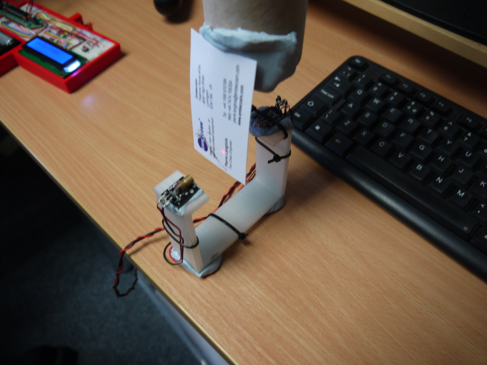
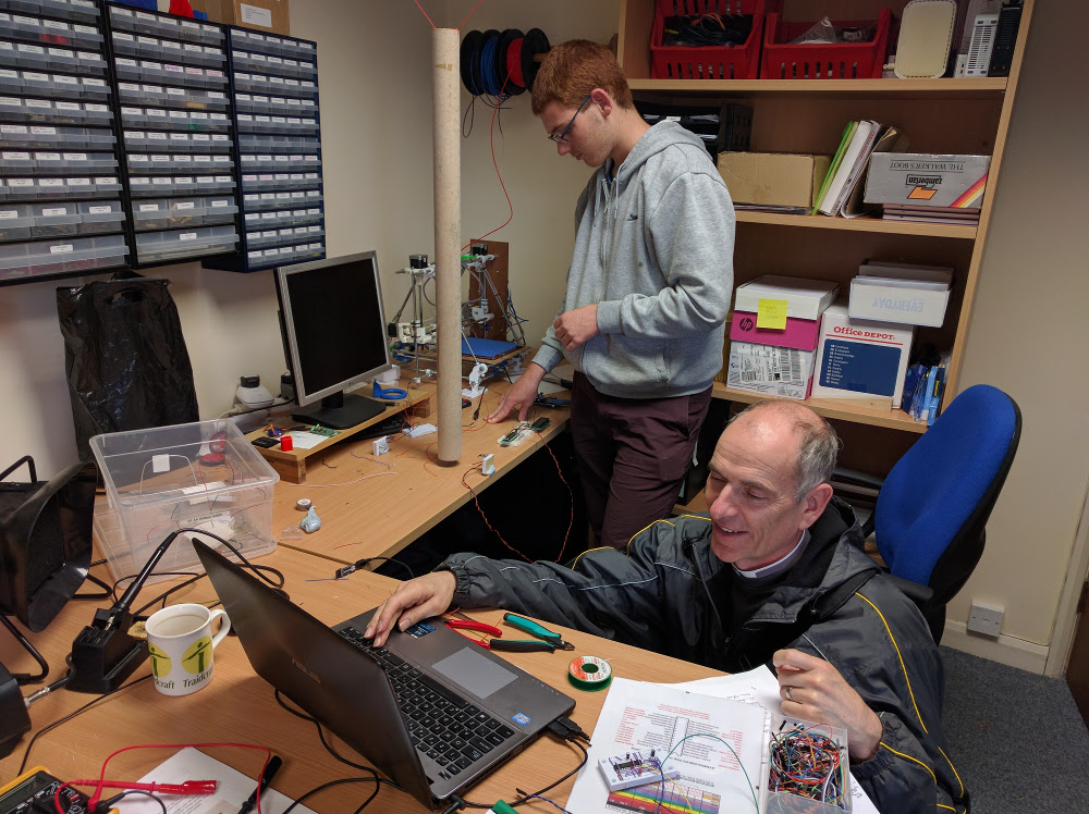
I first used the 3D printer when it was suggested that a yoke would be useful for positioning and supporting the laser and photo-resistor. FreeCAD was the chosen software and shortly after a crash course I had an acceptable design. Unfortunately, at the time the 3D printer wasn’t working, so it was eventually printed out on the Vicar’s personal 3D printer. After another test on the clock pendulum we decided that the yoke was effective but needed to fixed to the wall by something more substantial than blu tack.
A bracket was eventually designed along with a box for the main, and now only, breadboard. I did get to print these out on the printer in the office which was working by this point, although it was a bit temperamental. The box had to be printed in two parts because it was too big for the printer, but both parts fitted together perfectly using M3 nuts and bolts, and the bracket was a perfect fit on the yoke. A third part to the box was also printed on my last day to allow the batteries to be attached to the breadboard box, thus making it easier to transport/move the whole thing.
Conclusion
I found the work fulfilling and enjoyable; it was also new for me and unlike anything I’ve ever done before. I’ve learnt many new things and thoroughly enjoyed the fortnight I spent here. When testing the completed project Peter and I discovered this had been successful and there are now plans for the next work experience student to continue developing this project.