For my two weeks of work experience with Embecosm I was tasked with updating the Chiphack application note (EAN12) to use a different computer board, the Fomu. The end result of my work can be found here.
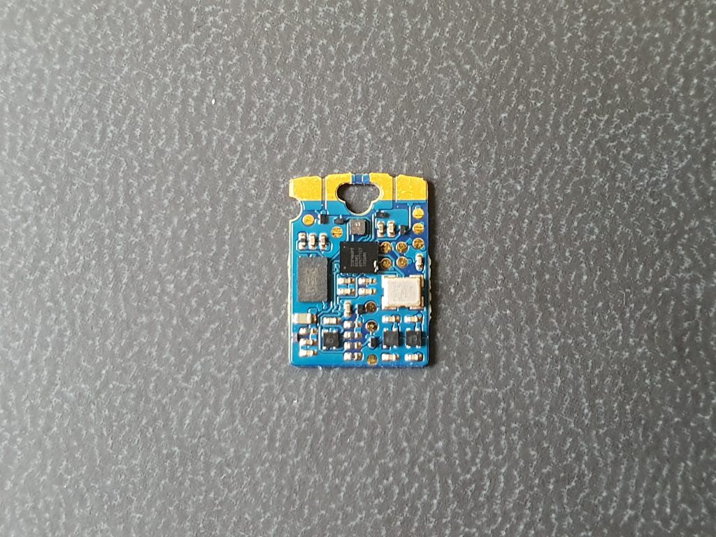
Fomu is a tiny FPGA (field programmable gate array) that fits inside your USB port! An FPGA which has a lot of re-programmable logic gates which can be connected together in order to create logic. What makes an FPGA special is that it can be reprogrammed, unlike normal computer chips where once the logic is made it is final. This is useful as FPGAs can be used to verify other computer chips before production or be used in situations where the chip may have to perform different functions.
The app note revolves around Verilog, which is a hardware description language that describes how a digital circuit is laid out. In this language you can create individual registers that hold data, wires and even individual logic gates. It handles common programming language syntax such as if, case and typical operators such as add, subtract, divide and boolean operators.
I enjoyed learning Verilog. It is something that is completely different from any other programming language I’ve used in the way that it gets implemented in hardware, but still recognizable in its grammar and syntax. This made learning interesting as things you’d take for granted in high level software languages are no longer as simple.
Getting started
My first day in Southampton was just about getting acquainted with the Fomu board, getting to know everyone and getting the Fomu’s LED blinking. I managed to program the Fomu with the basic RGB LED blink program and soon I was moving onto the app note. I grasped the layout and flow of creating chapters, sections and paragraphs, along with other types of additions.
Challenges
My first problem in trying to adapt the App note was that the Fomu has a very different set of IO (input and output) compared to the DE0 Nano (the previous board). In order to transmit data between my computer and the Fomu we needed a way of communication.
The board of the previous app note, the DE0 Nano had 26 I/O ports. The Fomu only has it’s two front buttons, as is it designed to primarily act like a USB device. However when trying to explain the basics of Verilog, implementing a USB device takes a lot of work and is out of reach for an App note about the basics of verilog!
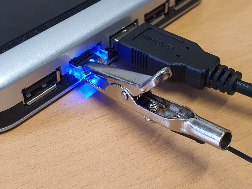
Although it is a bit ad-hoc, I managed to solve this problem by connecting to one of the front pads with a crocodile clip. This was then connected to a USB to UART cable. UART is a data transmission protocol, but it is simple to implement and is rather robust. This worked great and I managed to implement a simple UART transmission system on the Fomu so I can transmit data over to a computer.
As well as the app note, I created a Chiphack repository containing all the projects described in the app note. This is where I have my full implementations of the projects described in the app note.
The Docbook
Nearly everything in the app note was rewritten to accommodate the Fomu. In fact, the app note has gained 12 extra pages depspite the removal of multiple sections that were no longer relevant. The app note is written using DocBook, an XML based markup language for creating documentation in many different formats. This was at times daunting to work with but I quickly managed to add a lot more Verilog projects within the app note.
Projects
These are:
– Simple blinking,
– Using the front buttons,
– Encoding a message in the LED,
– Transmitting a message over UART,
– Transmitting binary numbers over UART,
– Fibonacci sequence over UART
– Pseudorandom numbers over the UART using a linear feedback shift register.
I hope these projects give a good starting point for development for the Fomu and Verilog and expose people to new concepts and ideas for them to put to new projects.
Linear-feedback Shift Registers
My favourite project with the Fomu is the pseudorandom bit stream using a linear feedback shift register. That’s a lot of jargon for “shuffling some bits about”. I enjoyed researching these and seeing different implementations using different mathematical concepts. By shifting and XORing a few bits, you can generate a stream of pseudorandom bits. This can be implemented in Verilog in just one line! This being deterministic (will output the same every time) and rather crude, it means it is not suitable for any serious uses as there are no sources of true randomization. The lack of a “cosmic background radiation detector” or a “wall of lava lamps” was a key point in this section!
New tools
In the project I also had to use git, the version control system. I hadn’t properly used git before apart from putting my own projects online but in the process of getting the app note uploaded and Chiphack repository uploaded I’ve learnt a lot more about the flow of git.
In the second week I met with the original author of the App Note, Dan Gorringe. Since 2014 (the original publication date), a lot of the tool flow for FGPAs has changed. Dan’s app note used a piece of software called Quartus. I’m glad that the tool flow for some FPGAs has moved away from clunky and proprietary software to open source tools such as Yosys and Nextpnr. The Fomu uses a Lattice Ice40, which is popular within the open source community as it is affordable compared to other series of FPGA. This is readily supported by open source tools and I had very few issues using them.
Closing thoughts
At times having a test bench to simulate our designs would’ve been helpful. Debugging via only the Fomu is slow, but I’m glad I focussed on just the Verilog. I would’ve also liked to explain further about the structure of a FGPA and about block ram and also more advance logic units. This would’ve been an oppertunity to also see how the open source tools such as yosys and nextpnr work and deal with having to program the ice40 fpga chip.
I do have plenty of future project ideas! Some do involve more IO pins! Some ideas include VGA output or an LED matrix.
Overall I’m happy with what I achieved with my Fomu. Explaining ideas and logic was tricky but I think I made most of it clear, especially with the included examples. I really enjoyed my time with Embecosm, I am thankful for the opportunity and the brilliant team that works there! Also thanks to Tim Ansell for creating the Fomu!