| Services - tools - models - for embedded software development |
|---|
| Services - tools - models - for embedded software development |
|---|

Application Note 6. Issue 1
February 2009
Copyright © 2009 Embecosm Limited
 | The document entitled " High Performance SoC Modeling with Verilator " by Jeremy Bennett of Embecosm is licensed under a Creative Commons Attribution 2.0 UK: England & Wales License. See the Legal Notice for details. |
Table of Contents
This document describes how to use Verilator [13] to create a fast cycle accurate SystemC model of a complete System-on-Chip from its Verilog RTL.
Cycle accurate models in C and SystemC are becoming an increasingly important part of the verification process, particularly for SoCs with performance critical embedded software. They represent a software friendly compromise, offering higher performance than traditional event-driven simulation, but greater accuracy than hand-written instruction set simulators (ISS) and transaction level models (TLM).
Typically such models follow 2-state, zero-delay synthesis semantics, offering an early insight into the behavior of the synthesized design. Applications include:
Detailed performance analysis of systems, based on the actual hardware implementation running with its embedded software.
Implementation of low level firmware, such as board support packages codecs and specialist device drivers, which rely on exact behavior of SoC peripherals.
Software optimization. This can be particularly important for codec development, where the performance depends critically on interaction between processor, memory, cache and MMU. In such scenarios, estimates by ISS and TLM can be out by a factor of 3, resulting either in wasted silicon, or chips that cannot meet their required performance.
If you are new to cycle accurate modeling tools, then this application note provides a hands-on introduction.
If you are experienced modeler, then this application note will offer suggestions for improving model performance, based on the author's long experience in this area.
While based on the open source tool, Verilator, the techniques described are equally applicable to commercial tools such as ARC VTOC or Carbon Design Systems Model Studio.
Verilator is an open source tool. This entire application note uses an open source SoC design (ORPSoC) and open source tools. The cycle accurate model is compared against simulation with Icarus Verilog [9]. The results are analyzed using GTKWave [8]. The ORPSoC application is built using the GNU C compiler.
Verilator has its own website (www.veripool.org), providing guidance for downloading, installing and using the tool. In particular this application note should be read in conjunction with the Verilator user guide.
SystemC is defined by IEEE standard 1666, and the standardization documents are the ultimate reference. The SystemC standard [10] is a free PDF download (a novelty for the IEEE). The open source reference implementation from OSCI includes an introductory tutorial.
The files making up the examples used in this application noted are comprehensively commented, and can be processed with Doxygen [5]. Each class, member and method's behavior, parameters and return value is described.
There is a wealth of material to support SystemC on the Internet.
The Open SystemC Initiative (OSCI) provides an open source reference implementation of the SystemC library, which includes tutorial material in its documentation directory. These may be accessed from the OSCI website (www.systemc.org).
OSCI also provide a number of public mailing lists. The help forum and the community forum are of particular relevance. Subscription is through the OSCI website (see above).
Embecosm is a consultancy specializing in open source tools, models and training for the embedded software community. All Embecosm products are freely available under open source licenses.
Embecosm offers a range of commercial services:
Customization of open source tools and software, including porting to new architectures.
Support, tutorials and training for open source tools and software.
Custom software development for the embedded market, including bespoke software models of hardware.
Independent evaluation of software tools.
For further information, visit the Embecosm website at www.embecosm.com.
Cycle accurate models provide an accurate description of the state of the model on each clock cycle. As such they represent a mid-point between traditional event driven simulation (providing detail within the clock cycle) and high level transaction models (providing details of bus transactions, but usually only approximate estimates of the cycle count).
Cycle accurate models are of particular value, because they reflect the level of detail seen by a software engineer using a chip. The software engineer generally cannot see what is happening within clock cycles.
There is some variation in the level of detail shown with specific modeling techniques. For example cycle accurate models generated by ARC VTOC from Verilog RTL will show the state of every state holding register in the model on each clock edge, and any asynchronous signal edge. Hand-written cycle accurate models within ARM SoC Designer will typically only show the state on the active edge of the clock cycle, and that state will be restricted to the external ports and defined internal registers.
Most cycle accurate models follow 2-state, zero delay synthesis semantics. In this way they are closer to the behavior of the actual chip than traditional 4-state event-driven simulation. However there is no absolute reason why cycle-accurate models could not follow 4-state simulation semantics.
Some cycle accurate models are written by hand—for example the cycle accurate models supplied by ARM for their processor cores. However the great majority of cycle accurate models are generated automatically from Verilog or VHDL RTL. There are two commercial products (ARC VTOC and Carbon Design Systems ModelStudio) and one free open source product (Verilator).
All these tools generate models in C/C++. However SystemC is becoming increasingly popular, and is generated by all the tools as well. However the reference OSCI SystemC simulator carries a serious performance penalty, and in all cases the model is a SystemC wrapper for the top level ports around a plain C/C++ model.
The performance penalty of SystemC wrappers should be a consideration when generating cycle accurate models. Performance can be particularly adversely affected by any ports of wider than 64-bits. The reference SystemC simulator has a very low-performance implementation of such ports.
The development of SystemC as a standard for modeling hardware started in 1996. Version 2.0 of the proposed standard was released by the Open SystemC Initiative (OSCI) in 2002. In 2006, SystemC became IEEE standard 1666-2005 [10].
Most software languages are not particularly suited to modeling hardware systems[1]. SystemC was developed to provide features that facilitate hardware modeling, in particular to model the parallelism of hardware, in a mainstream programming language.
An important objective was that software engineers should be comfortable with using SystemC, even though it is a hardware modeling language. Rather than invent a new language, SystemC is based on the existing C++ language. SystemC is a true super-set of C++, so any C++ program is automatically a valid SystemC program.
SystemC uses the template, macro and library features of C++ to extend the language. The key features it provides are:
A C++ class, sc_module, suitable for
defining hardware modules containing parallel
processes.
![[Note]](./images/note.png) | Note |
|---|---|
Process is a general term in SystemC to describe the various ways of representing parallel flows of control. It has nothing to do with processes in the Linux or Microsoft Windows operating systems. |
A mechanism to define functions modeling the parallel
threads of control within sc_module
classes;
Two classes, sc_port and
sc_export to represent points of
connection to and from a sc_module;
A class, sc_interface to describe the
software services required by a sc_port
or provided by a sc_export;
A class, sc_prim_channel to represent the
channel connecting ports;
A set of derived classes, of
sc_prim_channel,
sc_interface,
sc_port and
sc_export to represent and connect common
channel types used in hardware design such as signals, buffers and
FIFOs; and
A comprehensive set of types to represent data in both 2-state and 4-state logic.
The full specification is 441 pages long [10]. The OSCI reference distribution includes a very useful introductory user guide and tutorial [12].
[1] There are some exceptions, most notably Simula67, one of the languages which inspired C++. In some respects it is remarkably like SystemC.
The OpenRISC 1000 project forms part of the OpenCores organization (www.opencores.org). Its aim is to create a free open source computing platform, comprising:
An open source 32/64 bit RISC/DSP architecture;
A set of open source implementations of the architecture; and
A complete open source tool chain and operating system.
The OpenRISC 1000 project has resulted in Verilog for a 32-bit processor core, the OpenRISC 1200 (sometimes known as OR1200) and a complete reference System on Chip (SoC) design using that core, ORPSoC.
OpenRISC 1000 is a traditional RISC load-store architecture. Optional operands for multiplication and division may be added and there are optional data and instruction caches and MMUs.
A particularly useful feature is the l.nop
opcode. This takes an optional 16-bit constant operand, which is
placed in the low 16-bits of the instruction word. This field has no
impact on the execution of the instruction, but may be analyzed as
required by external test benches.
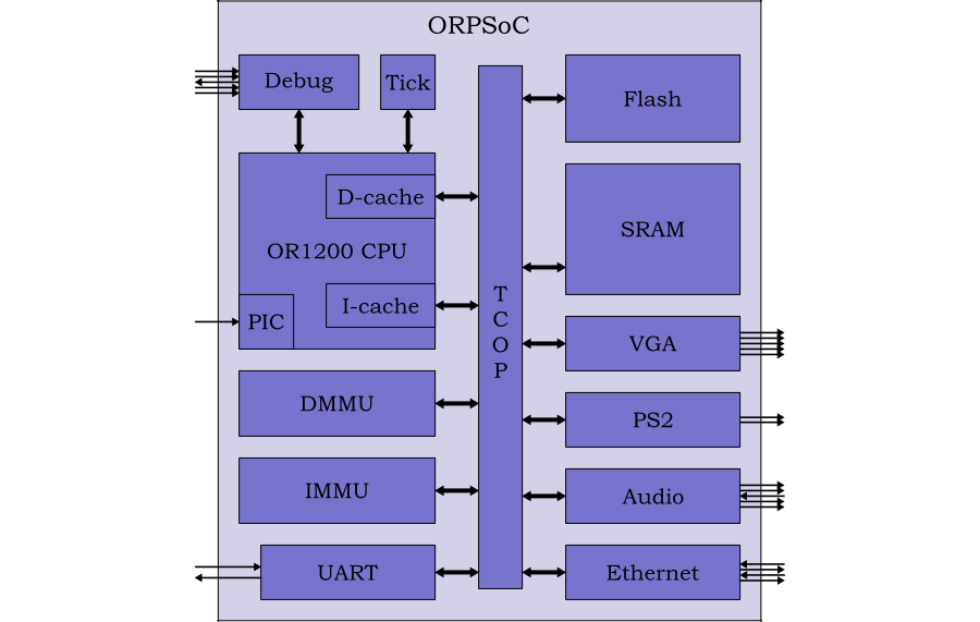
ORPSoC is a complete SoC based on the OpenRISC 1000. It combines the processor with SRAM, flash memory and a range of peripherals as shown in Figure 2.1.
The full design is around 150k gates + memories. It runs on standard Altera and Xilinx FPGA boards and is also available commercially from Flextronics.
Icarus Verilog [9] is an open source event driven simulator, offering an interface and behavior similar to commercial offerings such as Cadence NC, Synopsys VCS and Mentor Graphics ModelSim.
When developing cycle accurate models, it is important to compare behavior with event driven simulation, to understand any differences, and ensure they are not significant.
Icarus Verilog is capable of simulating ORPSoC at 1-2kHz on a standard PC running Linux.
Verilator [13] is an open source tool which generates cycle accurate C++ and SystemC models from synthesizable Verilog RTL. The models follow 2-state, zero delay, synthesizable semantics. Experimental versions are also able to process VHDL.
The functionality is similar to commercial offerings from ARC (VTOC) and Carbon Design Systems (Model Studio).
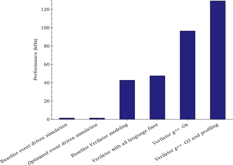
A Verilator SystemC model of ORPSoC simulates at up to 130kHz on a standard Linux PC.
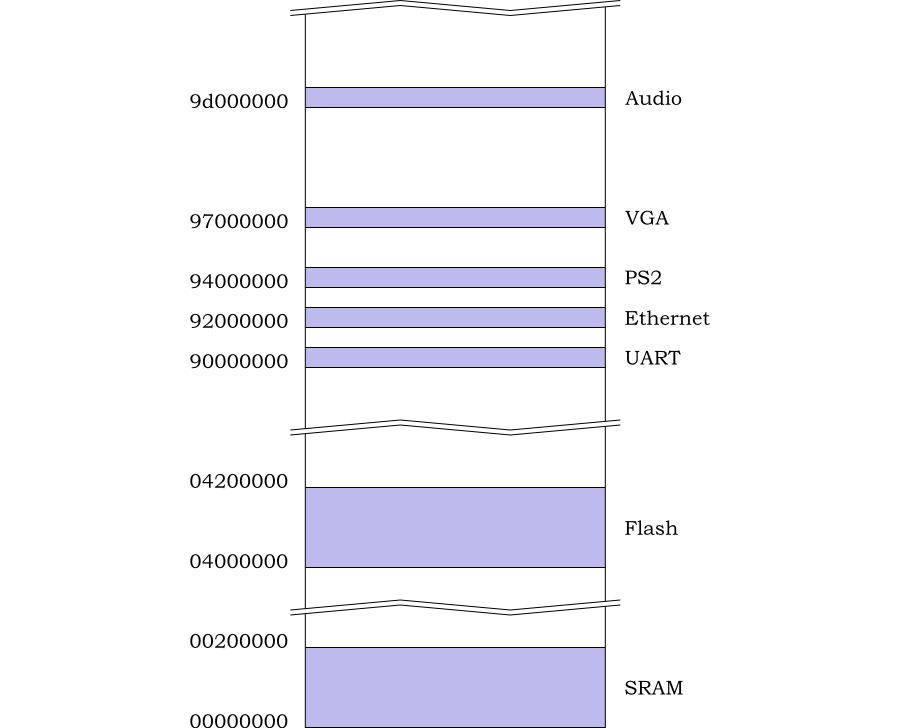
The demonstration system is based on a fully configured ORPSoC with data and instruction caches, data and instruction MMUs, multiply and divide instructions, 2MB Flash and 2MB SRAM. SRAM and all other memories are implemented as generic flip-flop memory. Flash memory is modeled as generic SRAM initialized from a file.
The memory map used is shown in Figure 3.1. This is slightly different from the memory map described in the ORPSoC documentation. However these are the values used in the standard distribution, which is a known working configuration.
During reboot, instruction fetches have 0x0400000 added. This means that the reboot sequence (which starts at 0x100) will fetch code from the Flash memory (0x04000100). This allows initial boot up code to be copied down into RAM.
The OpenRISC 1000 CPU incorporates a programmable interrupt controller, capable of handling up to 20 interrupt lines. These are assigned as shown in Table 3.1.
|
Number |
Assignment |
|---|---|
|
0-1 |
Unused |
|
2 |
UART |
|
3 |
Unused |
|
4 |
Ethernet |
|
5 |
PS/2 |
|
6-19 |
Unused |
Table 3.1. ORPSoC interrupt assignment
None of the peripherals are modeled—all external ports are tied off to appropriate values.
The behavior of ORPSoC is tracked through use of the OpenRISC 1000
l.nop instruction. These are incorporated in the
test applications as shown in Table 3.2
|
Opcode |
Action |
|---|---|
|
|
End simulation, with the value in GPR 3 as return code. |
|
|
Report the value in GPR 3. |
|
|
Print the value in GPR 3 as a character |
Table 3.2.
l.nop usage with the example ORPSoC platform
All other l.nop argument values are ignored.
The test bench implements a monitor function to detect a new
l.nop instruction. It implements the appropriate
functionality.
The test application is the the Dhrystone 2.1 benchmark [4]. A small support library based on the
l.nop instructions described in the previous
section is used to print out the results.
The OpenRISC 1000 no-operation instruction, l.nop
(32'h1500_0000), can take an optional 16-bit
immediate parameter, which forms the least significant 16-bits of the
instruction word. This value is ignored by the CPU, but may be
monitored by test benches
In ORPSoC this is used to provide I/O and control functions for the C code running on the processor.
l.nop 1
(32'h1500_0001). Terminates execution, with the
value in GPR 3 as return code. Thus the C library routine exit is
implemented as:
void exit (int i)
{
  asm("l.add r3,r0,%0": : "r" (i));
  asm("l.nop %0": :"K" (NOP_EXIT));
  while (1);
}
l.nop 2
(32'h1500_0002). Provides a reporting
function. The value in GPR 3 is printed in hex.
l.nop 3
(32'h1500_0003). Provides
printf functionality, with the arguments
passed according to the OpenRISC 1000 Application Binary Interface
(ABI). Not currently implemented.
l.nop 4
(32'h1500_0004). An Embecosm addition. The
least significant byte of GPR 3 is printed as a character. Thus
the C function putc can be implemented as:
void putc(int value)
{
  asm("l.addi\tr3,%0,0": :"r" (value));
  asm("l.nop %0": :"K" (NOP_PUTC));
}
More complex library routines (to print strings, numbers etc) can then be built up from this.
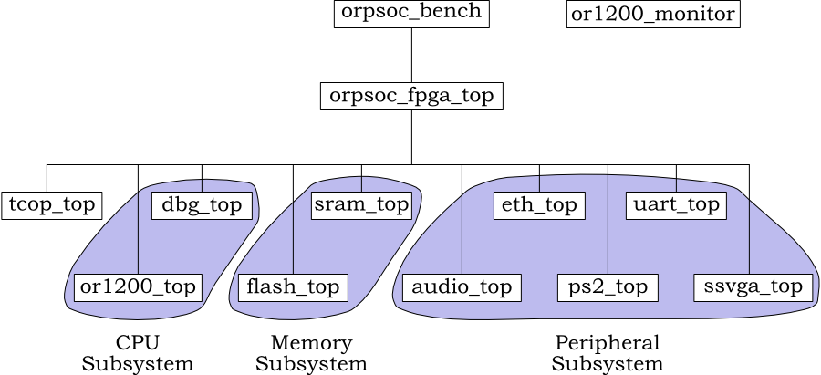
The Verilog hierarchy is shown in Figure 3.2.
The main hierarchy is the ORPSoC. The device under test (DUT)
starts at orpsoc_fpga_top. This instantiates the
modules for the bus interconnect (tcop_top), the
CPU/debug subsystem, the flash & SRAM memory subsystem and the
peripheral subsystem.
For event driven simulation with Icarus Verilog, the DUT is
instantiated by the top level test bench,
orpsoc. Alongside this sits the monitor module,
or1200_monitor, which implements the
l.nop functionality. For the Verilator model,
these functions will be provided by SystemC modules.
The files for this example are provided as a single compressed tar file, and include a snapshot of the current ORPSoC source tree for convenience. However the ORPSoC source may be downloaded from www.opencores.org and used independently if preferred.
The code is set up, so the ORPSoC code is not changed. Any files that are changed are placed in mirror directories in the custom code, and preferentially selected when building the model by specifying the search path.
![[Caution]](./images/caution.png) | Caution |
|---|---|
ORPSoC is constructed from several different projects (the CPU,
the debug unit, the peripherals etc). Each has source code in its
own directory, and each directory has its own
When the various components are brought together, the header search
paths (i.e. This is a potential source of confusion, but the current arrangement works, so has not been changed. |
The code is organized into a number of directories:
This contains the Makefile used to build
the system and the source files for the main Verilator test
bench in SystemC (OrpsocMain.cpp and
OrpsocMain.h).
orp_soc
This directory is a snapshot of the current ORPSoC source tree from www.opencores.org. Described in more detail below.
local
This directory is a shadow of the orp_soc
directory. Changed versions of files are placed here (thus
preserving the original source), and preferentially selected
when building the model by setting the search path.
sim
This directory contains the command files used to build event
driven simulation models using Icarus Verilog
(*.scr).
sysc-modules
This directory contains hand written SystemC modules which
are part of the SystemC test bench
(Or1200MonitorSC and
ResetSC).
verilator-model
This directory contains the command files to build the
various Verilator models (*.scr), a
class, OrpsocAccess, giving access to
signals inside the Verilator model, and a SystemC module,
TraceSC, generating VCD trace information
if required.
The original ORPSoC source tree snapshot can be found in
directory orp_soc of the distribution. The
subdirectories are:
bench
The test bench code. Subdirectory
verilog contains ORPSoC specific
Verilog code. These include timescale.v
specifying the `timescale for use across
the system, and bench_defines.v setting
system wide `define constants.
doc
Documentation about ORPSoC. The top level file
ORP.txt specifies a memory map and
interrupt assignment, but this does not match the actual
memory map used in the Verilog RTL (see Section 3.1).
Separate subdirectories, dbg_interface,
ethernet, or1200
and uart16550 document their
corresponding sub-systems and peripherals.
rtl
This is the Verilog RTL code for ORPSoC. The main
verilog subdirectory contains the top
level FPGA header file,
xsv_fpga_defines.v, and module
definition, xsv_fpga_top.v, together
with two "glue logic" modules, tc_top.v
and tdm_slave_if.v.
Separate subdirectories audio,
dbg_interface,
ethernet, mem_if,
or1200, ps2,
ssvga and
uart16550 contain the Verilog for the
core CPU, debug unit, Flash and SRAM memory interfaces and
peripherals. Directories with older versions of the RTL
for some peripherals are also present.
sw
This is the target software, which can be loaded into the ORPSoC Flash memory for various tests. They are all designed to be compiled using the OpenRISC 1000 tool chain (see [6]).
The utilities in the utils directory
must be built first, followed by the support libraries in
support. The other directories may be
built in any order. In general versions of the software are
provided for use with and without caches.
| Caution |
|---|---|
There does seem to be an assumption in these code examples
that ORPSoC is built with multiply
( Unfortunately this is not consistent with the default settings in the Verilog RTL. |
Initially six files are modified from the original ORPSoC source code. These modified files are placed in the corresponding custom code directory.
bench/verilog/bench_defines.v. The clock
half-period is set to 50 ns, corresponding to a clock rate of
10MHz.
bench/verilog/or1200_monitor.v. The standard
ORPSoC implementation includes a great deal of logging
functionality. This is not of relevance to the typical
applications of cycle accurate modeling in firmware
development. The custom version is stripped down to provide just
the custom l.nop functions (see Section 3.5).
bench/verilog/orpsoc_bench.v. The original
top level module was bench/verilog/xess_top.v
and represented a top level wrapper for a Xilinx FPGA, and
incorporated Verilog models of some of the peripheral behavior.
The intention for the Verilator SystemC model is that any
external functionality is provided by SystemC
modules. orpsoc_bench.v is a rewrite of
xess_top.v to provide a thin test bench to
allow the model also to be run under event-driven simulation.
In this simple implementation, the external ports are tied off, but could be connected to Verilog behavioral models in the future.
rtl/verilog/orpsoc_fpga_top.v. This is the
top level of the FPGA being modeled, and based closely on
xsv_fpga_top.v in the ORPSoC
source. However some aspects have been simplified. There is no
boot CPLD, or TDM conversion. Since all memory is internal, there
is no need for external memory ports for the Flash and SRAM.
This top level module of the actual device is completely
independent of any Verilog test bench (since with Verilator it
will use a SystemC test bench), so does not include
bench_defines.v.
rtl/verilog/orpsoc_fpga_defines.v. This is a
close derivative of the original
rtl/verilog/xsv_fpga_defines.v. However the
`define TARGET_VIRTEX is removed, since no
Xilinx (the manufacturer's of the Virtex FPGA range) IP is used. A
minor bug in the definition of APP_ADDR_PERIP
is also corrected.
rtl/verilog/or1200_defines.v. This customizes
the CPU for this application. Even though it is notionally a
FPGA design, caches and MMUs are enabled (by defining
OR1200_NO_DC, OR1200_NO_IC,
OR1200_NO_DMMU and
OR1200_NO_IMMU) and hardware division is
enabled (by defining OR1200_IMPL_DIV)
rtl/verilog/ssvga/ssvga_fifo.v,
rtl/verilog/ssvga/ssvga_top.v,
rtl/verilog/ssvga/ssvga_dpram_4x8x16.v and
rtl/verilog/ssvga/ssvga_dpram_4x16x16.v. Almost
the entire ORPSoC design provides options to use different
manufacturer's RAM block models, or a generic flip-flop
model. This is managed through `ifdef
directives, using `define values from the main
header files.
The exception is the VGA peripheral, which assumes availability of
Xilinx RAMB4 models. To fix this, modified
versions of the two VGA source files
(rtl/verilog/ssvga/ssvga_fifo.v and
rtl/verilog/ssvga/ssvga_top.v), together with
suitable generic dual ported RAM blocks
(rtl/verilog/ssvga/ssvga_dpram_4x8x16.v and
rtl/verilog/ssvga/ssvga_dpram_4x16x16.v).
To facilitate building the models, a Makefile is
provided in the top level directory. Three targets are
provided.
make simulate will run an event driven
simulation using Icarus Verilog (in the sim
sub-directory).
make verilate will build and then run a SystemC cycle accurate model using Verilator
make clean will clean out all generated files.
For the simulate target, the time used by the iverilog compilation and the vvp execution are recorded (with time -p).
For the verilate target, the time used to create the Verilated model and the execution time of the complete SystemC model are recorded (also with time -p).
The Verilog source files and header directories to be used when
modeling are specified in command files in the
sim and verilator-model
directories for event driven simulation and cycle accurate SystemC
modeling respectively. The default is
cf-baseline.scr, but an alternative may be
specified through the COMMAND_FILE macro. For
example.
make simulate COMMAND_FILE=cf-baseline-5.scr
When writing command files, a number of macros may be used for clarity.
$BENCH_DIR
Replaced by the location of the original ORPSoC test bench
Verilog directory. This depends on where the code has been
unpacked. For example if it is in
~/orp_soc, then this macro will be
replaced by ~/orp_soc/bench/verilog.
$RTL_DIR
Replaced by the location of the original ORPSoC device
Verilog directory. This depends on where the code has been
unpacked. For example if it is in
~/orp_soc, then this macro will be
replaced by ~/orp_soc/rtl/verilog.
$BENCH_LOCAL
Replaced by the location of the directory containing custom
test bench Verilog. This is always in a fixed place in the
hierarchy and the macro will be replaced by a reference to
bench/verilog.
$RTL_LOCAL
Replaced by the location of the directory containing custom
device Verilog. This is always in a fixed place in the
hierarchy and the macro will be replaced by a reference to
rtl/verilog.
Additional flags may be passed to Icarus Verilog and Verilator by
use of the VFLAGS macro. Of particular use are the
flags to generate a VCD trace:
make simulate VFLAGS=-DORPSOC_DUMP
make verilate VFLAGS=-trace
The target application is a Dhrystone simulation. The number of
loops through this simulation can be set using the
NUM_RUNS macro, which defaults to 1.
make verilate NUM_RUNS=100
| Note |
|---|---|
The software build is not sensitive to changes in the value of
|
Verilator is not a complete alternative to traditional event driven simulation. Its value is for modeling where the detail (and simulation performance hit) of 4-state logic and intra-cycle behavior are not needed, and where efficient interfacing to software environments are essential.
It is thus important that the Verilator model is consistent throughout with event driven simulation, and so the initial stage of any Verilator modeling is to build the baseline simulation against which it will match. There are three additional reasons why such a baseline simulation is important
Because Verilator follows 2-state, zero delay synthesis semantics, some changes will be needed to the source code. These most commonly will involve substituting non-synthesizable parts of the design. Checking the Verilator model using the substituted code against the original event driven simulation is an essential step.
Verilator models are used typically in environments where performance is very important. In many cases it is possible to rewrite key parts of the Verilog to be far more efficient when modeled cycle accurately. This is commonly the case for memories, where for example, it is not necessary to individually buffer each input and output bit. Again it is essential to be able to compare rewritten code against the original simulation behavior.
Finally Verilator includes powerful linting tools, and will typically throw up huge numbers of diagnostic warnings. It makes a great deal of sense to address all these warnings. They address issues that may cause problems with synthesis and gate level verification. They also highlight areas that can badly impact on model performance.
The command file for this baseline simulation is found in
sim/cf-baseline.scr.
The first part of this file sets up the header directories. The local custom directories are specified in preference where appropriate.
+incdir+$BENCH_LOCAL
+incdir+$BENCH_DIR
+incdir+$RTL_LOCAL
+incdir+$RTL_LOCAL/or1200
+incdir+$RTL_DIR/or1200
+incdir+$RTL_DIR/dbg_interface
+incdir+$RTL_DIR/audio
+incdir+$RTL_DIR/ethernet
+incdir+$RTL_DIR/ps2
+incdir+$RTL_DIR/uart16550
+incdir+$RTL_DIR/ssvga
As noted earlier, there are multiple instances of
timescale.v, with different values for time unit
and precision. However with all Verilog files will find the first
once, which is in $BENCH_DIR
(1ns/10ps).
There are three test bench files: the main ORPSoC test bench and the
ORPSoC monitor for l.nop opcodes.
$BENCH_LOCAL/orpsoc_bench.v
$BENCH_LOCAL/or1200_monitor.v
The top level module of the DUT, orpsoc_fpga_top
is then specified. The bus interconnect instantiated by
orpsoc_fpga_top, tc_top, is also
specified.
$RTL_LOCAL/orpsoc_fpga_top.v
$RTL_DIR/tc_top.v
The sub-components of the FPGA are then specified: the OR1200 CPU, the debug interface, flash and SRAM and audio, Ethernet, keyboard, UART and video peripherals.
The simulation is run with the command:
make simulate COMMAND_FILE=cf-baseline.scr NUM_RUNS=1000
The Makefile compiles the target software using
the OpenRISC 1000 tool chain, then compiles the simulation with
iverilog and runs it with
vvp. The compilation is error free:
cd sim/run && time -p iverilog -c iv-processed.scr
real 1.75
user 1.48
sys 0.30
The output from the execution is:
$readmemh(../src/flash.in): Not enough words in the read file for requested rang
e.
(orpsoc_bench.i_orpsoc_fpga.uart_top) UART INFO: Data bus width is 32. Debug Int
erface present.

(orpsoc_bench.i_orpsoc_fpga.uart_top) UART INFO: Doesn't have baudrate output

Execution starts, 1000 runs through Dhrystone
Begin Time = 5
End Time   = 116421
OR1K at 10 MHz  (+PROC_6)
Microseconds for one run through Dhrystone: 116us / 1000 runs
Dhrystones per Second:                      8589
117975052.00 ns: l.nop report (deaddead)
117986152.00 ns: l.nop exit (00000000)
real 839.00
user 837.40
sys 0.57
The warning from $readmemh can be ignored—the
OpenRISC 1000 utilities do not pack the program image up to the full size of
the actual memory to save file space. There are then a couple of
diagnostic messages from the UART
The remainder of the output is generated by the target OpenRISC 1000 program
executing within the model. The output is generated by use of
l.nop 4, with a report at the end
(deaddead) using l.nop 2
and termination with return code 0 using
l.nop 1.
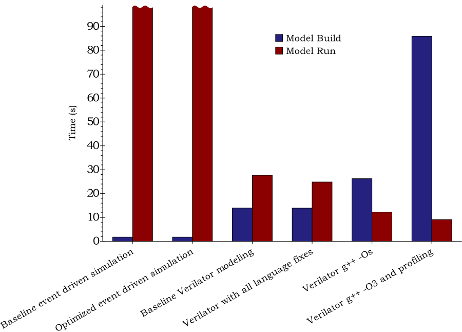
These data sets were all recorded on the author's workstation, a 2GHz Core2 Duo E2180, with 1MB cache/processor and 2GB RAM, running Fedora 9 Linux. In all cases 1000 loops through the Dhrystone benchmark was used. The figures presented are the average of at least 6 runs.
Total processor time for elaboration was 1.78 s and for simulation was 796.84 s. Net simulation performance was 1.48kHz.
| Note |
|---|---|
Throughout this application note, results will be given showing:
Cycle accurate models are typically used in scenarios, where the model is created once and used many times, so the run-time performance is the critical figure. |
Before building the Verilator model it is necessary to consider the
test bench, which will replace orpsoc.v and
or1200_monitor.v. This chapter looks at the overall
structure of the test bench, and the detailed implementation of the pure
SystemC components.
There are also a number of components which tie in closely with the actual Verilator model (for example to access signals in the model, or to generate VCD traces from the underlying model). These are covered in the chapter on building the Verilator model (Chapter 6).
The structure of the SystemC test bench is not that different to the
Verilog test bench used with event driven simulation (see Chapter 4). The DUT is provided by the Verilator
model (class Vorpsoc_fpga_top) and the monitor for
l.nop is hand-written as a SystemC class,
Or1200MonitorSC.
Two further SystemC classes are needed, one to generate a reset
signal (ResetSC) and a second to provide VCD
trace functionality of the underlying Verilator model
(TraceSC).
The top level of the test bench (the equivalent of
orpsoc_bench) is provided by the
sc_main function.
This SystemC module class is automatically generated by
Verilator. The class name is taken from the top level module
(orpsoc_fpga_top preceded by V.
The input and output ports of this module are mapped to SystemC
sc_in and sc_out ports. Single
bit ports are of type bool. Larger ports are of
type uint32_t.
In this example there are no ports larger then 32 bits. If there were, then they would use either uint64_t or the SystemC sc_bv types.
| Note |
|---|---|
SystemC offers its own set of types for ports of arbitrary
width. However in the reference library, the implementation of
these types can be very inefficient. Hence the preference for
|
| Caution |
|---|---|
Verilator also supports |
The functionality of this class is identical to that of its Verilog
counterpart. On each positive clock edge, the freeze signal for the
write back pipeline stage in the CPU control unit is checked. If the
value is clear, the current instruction being executed is read. If
the instruction is a special l.nop instruction,
the appropriate behavior is implemented.
The class has a single port, clk of type
sc_in<bool>, which is connected to the
system clock.
Access to signals within the Verilator ORPSoC model is
provided by the OrpsocAccess class, an
instance of which is passed to the constructor.
The implementation of OrpsocAccess is
covered in the chapter on Verilator modeling Chapter 6. It provides a number of methods to
access signals in the model. Those of particular interest here
are:
getWbFreeze
Gives the bool value of the CPU control unit
write back freeze signal, wb_freeze.
getWbInsn
Gives the uint32_t value of the CPU control
unit write back instruction, wb_insn.
getGpr (regNum)
Get the value of the ORPSoC GPR
regNum from the CPU register file in
rf_a.
The constructor declares a SystemC method,
checkInstruction, which will check for
a l.nop instruction on the positive edge of
each clock.
This function is called on the positive edge of each clock
cycle. It uses the accessor class getWbFreeze
and getWbInsn functions to check for special
l.nop instructions. It implements behavior as
follows:
l.nop 1
Gets the value in GPR 3 using the accessor
getGpr function, which is the return
code from the function. Prints out a time stamp (using the
SystemC function, sc_time_stamp)
followed by a message that the simulation is exiting with
the return code obtained. Then calls the SystemC function,
sc_stop to terminate model execution.
l.nop 2
Gets the value in GPR 3 using the accessor
getGpr function. Prints out a time
stamp (using the SystemC function,
sc_time_stamp) followed by a message
reporting the value found in GPR 3.
l.nop 3
This is the printf function, but is not
implemented. Prints out a time stamp (using the
SystemC function, sc_time_stamp)
followed by the text "printf".
l.nop 4
Gets the value in GPR 3 using the accessor
getGpr function, the bottom 8 bits of
which are the character to print. Prints the character to
standard output, and then flushes it. This avoids any issues
with C++ library buffering if redirecting the output during
a slow run.
This module is used to generate a reset signal at start up for a defined number of clock cycles.
It takes as input port the system clock and for convenience generates both active high and active low reset signals. Only the active low reset signal is used in this application note.
sc_core::sc_in<bool>   clk;
sc_core::sc_out<bool>  rst;
sc_core::sc_out<bool>  rstn;
The constructor takes an optional argument of the number of cycles of reset to provide at start up. If not given, this defaults to 5. This is used to initialize the reset counter.
A SystemC method, driveReset is declared
which is sensitive to the negative edge of the clock. Releasing
the reset on the negative edge of the clock in a cycle-accurate
environment means the model will see the released reset first on a
positive clock edge.
These classes implement respectively VCD tracing and signal access in the Verilator model. Because they are so intimately involved with the Verilator model, their description is postponed to that chapter (Chapter 6).
The top level of the SystemC model, corresponding to
orpsoc_bench.v is found in
OrpsocMain.cpp. This defines the SystemC
sc_main function.
This includes the header file OrpsocMain.h, which
has the system wide definitions, and corresponds to the Verilog
definitions in orpsoc_defines.h.
The headers for all the classes that will be used must also be included:
#include "OrpsocMain.h"

#include "Vorpsoc_fpga_top.h"
#include "OrpsocAccess.h"
#include "TraceSC.h"
#include "ResetSC.h"
#include "Or1200MonitorSC.h"
A SystemC clock, clk is declared of type
sc_clock, which will form the main system clock.
This followed by declarations of signals to connect all the ports on the main ORPSoC module. These include reset, JTAG and all the external peripherals (audio, Ethernet, keyboard, UART and video).
Variables are declared to reference the accessor class
(accessor) and SystemC modules
(orpsoc, trace,
reset, monitor). New instances
of these are then instantiated.
The modules are then connected to the signals. The vast majority of
these are to the main Vorpsoc_fpga_top
instance. The main clock signal is used for both the main system
clock and JTAG clock, thus ensuring they will be synchronous.
There are no explicit peripheral models, or JTAG interface, so peripheral input signals are tied off appropriately.
With the modules connected, the model is set to run for an
indefinite period by a call to the SystemC function
sc_start. Execution will only terminate if the
program being executed includes a l.nop 1
opcode, which will cause the monitor module to
call the SystemC function sc_stop.
If and when execution does terminate, the space allocated for
modules is deleted before the sc_main function
returns.
Building a Verilator model has a number of traps for the unwary
Verilator is a synthesis technology, so will reject any non-synthesizable constructs. This can be a particular problem with third party models of memories.
Verilator by default handles Verilog 1995, 2001, 2005 and
SystemVerilog. The last can be a particular nuisance, since
SystemVerilog contains a number of new keywords, which can break
older Verilog code (for example do is now a
keyword, but has commonly been used as the name for the data out
port of a memory).
Verilator has a very strict linting system, which flags issues which can affect model performance.
So it is not uncommon for Verilator to immediately throw errors on RTL which is supposedly clean and synthesizable.
It is simple to take the baseline command file from the Icarus Verilog
simulation (see Chapter 4) and modify
it for use with Verilator. All that is needed is to remove the
reference to orpsoc_bench.v and
or1200_monitor.v.
As noted earlier, there are multiple instances of
timescale.v, with different values for time unit
and precision. Now all the Verilog files form a single SoC design, and
all their header directories are specified using
+incdir+. So now all components will use the same
timescale.v, the copy in
$RTL_DIR (orp_soc/rtl/verilog). This specifies
1ps/1ps, a different value to that used in
simulation, but does not have any practical impact.
The model can be built with:
make verilate COMMAND_FILE=cf-baseline.scr
This immediately produces a slew of warnings and errors
%Warning-CASEX: ../orp_soc/rtl/verilog/or1200/or1200_alu.v:207: Suggest casez (w
ith ?'s) in place of casex (with X's)
%Warning-CASEX: Use "/* verilator lint_off CASEX */" and lint_on around source t
o disable this message.
%Warning-CASEX: ../orp_soc/rtl/verilog/or1200/or1200_alu.v:278: Suggest casez (w
ith ?'s) in place of casex (with X's)
%Warning-CASEX: ../orp_soc/rtl/verilog/or1200/or1200_alu.v:280: Suggest casez (w
ith ?'s) in place of casex (with X's)

...

%Warning-CASEX: ../orp_soc/rtl/verilog/or1200/or1200_mult_mac.v:196: Suggest cas
ez (with ?'s) in place of casex (with X's)
%Error: ../orp_soc/rtl/verilog/mem_if/flash_top.v:210: syntax error, unexpected
')'
%Error: Cannot continue
%Error: Command Failed /home/jeremy/tools/verilator/verilator-3.700/verilator_bi
n -Mdir . -sc -f v-processed.scr
The first step is to turn off the warnings, to allow the errors to
stand out, using the VFLAGS macro.
make verilate COMMAND_FILE=cf-baseline.scr VFLAGS=-Wno-lint
The result of this is:
%Error: ../orp_soc/rtl/verilog/mem_if/flash_top.v:210: syntax error, unexpected
')'
%Error: Cannot continue
%Error: Command Failed /home/jeremy/tools/verilator/verilator-3.700/verilator_bi
n -Mdir . -sc -f v-processed.scr
Looking at the source file concerned
(flash_top.v) shows the problem at line 210:
// synopsys translate_off
integer fflash;
initial fflash = $fopen("flash.log");
always @(posedge wb_clk_i)
        if (wb_cyc_i)
The problem is the use of the multi-channel descriptor form of
$fopen, which is not supported by Verilator.
There are two solutions to this problem. A simple solution is to turn
this into a standard file descriptor open:
initial fflash = $fopen("flash.log", "w");
The alternative is to recognize that logging flash accesses is not of great interest to this model (it is something of greater concern to a hardware verification engineer with event-driven simulation).
Furthermore, this model will not be using external flash memory, and
only loads its image from file at start up. This is the time to replace
flash_top.v by a much simpler model suitable for
cycle accurate use in our environment. This is provided in the local
directory, rtl/verilog/mem_if/flash_top.v.
![[Tip]](./images/tip.png) | Tip |
|---|---|
There is always a balance between making the least possible change (minimizing the risk of introducing behavioral bugs) and complete replacement. In general making the least possible change is the right strategy. However memories are usually central to a model's performance, and can often be full of RTL structures, which are irrelevant to cycle-accurate modeling—for example buffering each input and output bit. In these cases (as here), it is worth replacing the original completely. The value of having a baseline event driven simulation model now becomes clear: VCD traces can be used to verify that the behavior of replacement models is consistent. |
The command file is modified to use the reference to this local
version instead of the standard flash_top.v:
$RTL_LOCAL/mem_if/flash_top.v
Verilator is now re-run:
make verilate COMMAND_FILE=cf-baseline-2.scr VFLAGS=-Wno-lint
Verilator immediately hits its next error.
%Error: ../orp_soc/rtl/verilog/mem_if/sram_top.v:236: syntax error, unexpected '
)'
%Error: Cannot continue
%Error: Command Failed /home/jeremy/tools/verilator/verilator-3.700/verilator_bi
n -Wno-lint -Mdir . -sc -f v-processed.scr
Exactly the same issue with logging in the SRAM model:
integer fsram;
initial begin
        fsram = $fopen("sram.log");
        for (i = 0; i < 2097152; i = i + 1)
                mem[i] = 0;
As before, the solution in this case is to replace
sram_top.v with a simplified version suitable for
cycle accurate modeling. We then run Verilator again:
make verilate COMMAND_FILE=cf-baseline-3.scr VFLAGS=-Wno-lint
The next problem materializes:
%Error: ../orp_soc/rtl/verilog/ethernet/eth_wishbone.v:564: syntax error, unexpe
cted do, expecting IDENTIFIER
%Error: Cannot continue
%Error: Command Failed /home/jeremy/tools/verilator/verilator-3.700/verilator_bi
n -Wno-lint -Mdir . -sc -f v-processed.scr
| Note |
|---|---|
It will be clear that getting rid of errors in Verilator can be quite tedious, because most errors will cause compilation to stop. This is a common problem, even with commercial tools, because of the nature of Verilog. All files depend on each other (they are not modular in the software sense), so a failure in one affects all the others in unknown ways. |
This error is a consequence of Verilator being able to process all
flavors of Verilog and SystemVerilog. In SystemVerilog
do is a keyword, and may not be used as a
variable.
The correct fix is to replace the occurrences with a different
variable name. However the short term fix is to restrict Verilator
to just a particular language, in this case Verilog according to IEEE
1364-2001. This is achieved by using Verilator's
-language option:
make verilate COMMAND_FILE=cf-baseline-3.scr \
              VFLAGS="-Wno-lint -language 1364-2001"
The next error is an example of Verilator requiring synthesizable RTL as its input:
%Error: ../orp_soc/rtl/verilog/ps2/ps2_translation_table.v:181: Unsupported: Ver
ilog 1995 reserved word not implemented: repeat
%Error: ../orp_soc/rtl/verilog/ps2/ps2_translation_table.v:181: syntax error, un
expected '(', expecting case or casex or casez or if
%Error: Cannot continue
%Error: Command Failed /home/jeremy/tools/verilator/verilator-3.700/verilator_bi
n -Wno-lint -language 1364-2001 -Mdir . -sc -f v-processed.scr
Here is the code in ps2_translation_table.v which
causes the problem.
always@(posedge clock_i or posedge reset_i)
begin
    if ( reset_i )
        ram_out <= #1 8'h0 ;
    else if ( translation_table_enable )
    begin:get_dat_out
        reg [7:0] bit_num ;

        bit_num = translation_table_address[4:0] << 3 ;

        repeat(8)
        begin
            ram_out[bit_num % 8] <= #1 ps2_32byte_constant[bit_num] ;
            bit_num = bit_num + 1'b1 ;
        end
    end
end
According the the IEEE standard, repeat is not
synthesizable, even if, as in this case, it has a constant argument
and a clear synthesizable meaning.
The issue is confused, because some commercial synthesis tools will accept constructs like this, even though they are not permitted in the standard.
In this case the fix is very simple. The contents of the always block are just written out in full:
        ram_out[bit_num % 8] <= #1 ps2_32byte_constant[bit_num] ;
        bit_num = bit_num + 8'b1 ;
        ram_out[bit_num % 8] <= #1 ps2_32byte_constant[bit_num] ;
        bit_num = bit_num + 8'b1 ;

        <5 more times>

        ram_out[bit_num % 8] <= #1 ps2_32byte_constant[bit_num] ;
        bit_num = bit_num + 8'b1 ;
The modified version of ps2_translation_table.v
is placed in the local directory
(rtl/verilog/ps2), the command file altered and
Verilator rerun.
This time Verilator does not encounter any errors, but a whole load
of new warnings. The flag -Wno-lint turns off many
warnings, but not all. Two warnings in particular are common:
Warning COMBDLY. Use of non-blocking assignment
(delayed assignment) in combinatorial always
blocks. This issue is discussed in more detail in Chapter 7, but indicates a coding style that
may cause unexpected behavior in a cycle accurate model.
Warning UNOPTFLAT. The presence of
combinatorial loops, which can seriously damage model
performance. This issue is discussed in more detail in Chapter 7, where it is a fruitful source of
performance enhancements.
For now both these warnings can be explicitly turned off using the
flags -Wno-COMBDLY and
-Wno-UNOPTFLAT.
make verilate COMMAND_FILE=cf-baseline-4.scr \
   VFLAGS="-Wno-lint -Wno-COMBDLY -Wno-UNOPTFLAT -language 1364-2001"
This is sufficient for Verilator to successfully process the entire source and generate a model. However the complete SystemC model will not built—some header files needed by the C++ code are missing.
These headers are part of the system for accessing signals within the Verilator model. These must now be added.
By default Verilator does not provide access to internal signals within the Verilog hierarchy. However it provides two mechanisms for such access:
Mark the signal with a verilator public
comment. It may then be accessed directly from the SystemC test
bench.
Define a function and/or task to access the signal, and mark it
with a verilator public comment. This is
the preferred approach.
In either case, values of up to 64 bits are stored in the smallest appropriate C++ unsigned type. (uint8_t, uint16_t, uint32_t, uint64_t).
In practice SystemC programs will just use bool, uint32_t and uint64_t for the results, relying on C++ to automatically cast the values. This is then consistent with the set of types used for SystemC module signals.
Signals wider than 64-bits are represented as arrays of uint32_t, with the least significant bits in the lowest numbered element. Where the number of bits is not a multiple of 32, the odd bits are the least significant bits of the highest numbered element.
For example reg [47:0] r would be
represented in a C++ array,
uint32_t r[2]. Bits [31:0] would be in C++
array r[0] and bits [47:32] would be in the 16
least significant bits of the C++ array r[1].
| Caution |
|---|---|
Verilator cannot handle results wider than 64 bits from
functions. For such signals either tasks must be used (with result
via an |
| Caution |
|---|---|
With cycle accurate models, such as those created by Verilator it is only meaningful to update signals which are state-holding, that is the registers in sequential logic. Updating wires, or registers used only in combinatorial logic, will have no effect. |
In general Verilator flattens the Verilog module hierarchy when generating C++ or SystemC models, and will generate just a small number of C++ classes (very often just one).
However when direct access to a signal is needed, Verilator must expose the hierarchy, and will define multiple C++ classes, corresponding to the modules in the hierarchy to the signal.
For example with ORPSoC the top level SystemC module generated
is Vorpsoc_fpga_top. As shown in Section 5.2.1, this was used when instantiating the main
ORPSoC module:
orpsoc = new Vorpsoc_fpga_top ("orpsoc");
However if the wb_freeze signal in the CPU
control unit were to be accessed additional C++ classes would be
declared. The signal's hierarchical references is:
orpsoc_fpga_top.or1200_top.or1200_cpu.or1200_ctrl.wb_freeze
Verilator creates public classes for all the intermediate modules in
this hierarchy (or1200_top,
or1200_cpu and or1200_ctrl),
each of which includes a pointer to the next level down in the
hierarchy. Thus the wb_freeze can be accessed
from C++ through the top level module (orpsoc,
instantiated as above) as follows:
orpsoc->v->or1200_top->or1200_cpu->or1200_ctrl->wb_freeze
Notice that there is one intervening class, v,
after the top level module. This is explained later.
To access these, the header files for the intervening modules must be included. These take their name from the top level module, and the intermediate module, thus:
#include "Vorpsoc_fpga_top_or1200_top.h"
#include "Vorpsoc_fpga_top_or1200_cpu.h"
#include "Vorpsoc_fpga_top_or1200_ctrl.h"
All these intermediate modules are plain C++ classes, not SystemC
modules. This is the reason for the intervening class,
v. The top level class,
Vorpsoc_fpga_top is a
SystemC module. However it is only a wrapper for the plain C++
Verilator model of the top level module. Thus the
v points to the plain C++ model of the top level
module, and is inserted after the SystemC module at the top
level. It has its own header, which must be included:
#include "Vorpsoc_fpga_top_orpsoc_fpga_top.h"
| Note |
|---|---|
Verilator does provide a mechanism for accessing signals without
breaking up the C++ into separate modules. This is achieved by use
of the However if access to a diverse range of signals in many modules is required, this may be necessary to avoid the performance penalty of breaking the model into many small classes. |
The wb_freeze signal is used as an example of
direct access. It is declared in
rtl/verilog/or1200/or1200_ctrl.v, where it is
an input to the module.
input wb_freeze;
To declare the signal public, a
verilator public comment must be inserted
before the closing semi-colon.
input wb_freeze /* verilator public */;
| Caution |
|---|---|
The comment must be before the closing semi-colon. |
Verilator will generate all the intervening classes for the signal's full hierarchy (see Section 6.2.1):
orpsoc_fpga_top.or1200_top.or1200_cpu.or1200_ctrl.wb_freeze
The signal can then be accessed from C++, having included the headers for all the intermediate classes:
#include "Vorpsoc_fpga_top_orpsoc_fpga_top.h"
#include "Vorpsoc_fpga_top_or1200_top.h"
#include "Vorpsoc_fpga_top_or1200_cpu.h"
#include "Vorpsoc_fpga_top_or1200_ctrl.h"

...

  Vorpsoc_fpga_top *orpsoc = new Vorpsoc_fpga_top ("orpsoc");

...

  bool  wb_freeze = orpsoc->v->or1200_top->or1200_cpu->or1200_ctrl->wb_freeze;
The recommended way to access signals is via a Verilog task or function. These are converted by Verilator into C++ class functions. Inputs to tasks and functions become arguments passed by value to the C++ function, while outputs become arguments passed by reference (and so can be used for results).
Verilog tasks become C++ void functions, while Verilog functions become C++ functions with a return type of a size appropriate to the result of the Verilog function (uint8_t, uint16_t, uint32_t or uint64_t).
| Caution |
|---|---|
One limitation of Verilator is that it cannot handle functions which return values of more than 64 bits. If this is required, an output argument of either a task or function should be used. |
For an example consider the 32-bit wb_insn
register in the ORPSoC control unit. It's full hierarchical
reference is:
orpsoc_fpga_top.or1200_top.or1200_cpu.or1200_ctrl.wb_insn
It is declared as:
reg [31:0] wb_insn;
A Verilog function is declared to give access to this register:
`ifdef verilator
   function [31:0] get_wb_insn;
      // verilator public
      get_wb_insn = wb_insn;
   endfunction // get_wb_insn
`endif
There are two items of note. First the function must include a
verilog public comment immediately after its
declaration. Secondly functions without inputs are not permitted in
IEEE 1364-2001, so this code must only be exposed to Verilator
processing.
Verilator defines verilator, so this can be
achieved by surrounding the code with
`ifdef verilator and
endif.
The signal can then be accessed from C++, having included the headers for all the intermediate classes:
#include "Vorpsoc_fpga_top_orpsoc_fpga_top.h"
#include "Vorpsoc_fpga_top_or1200_top.h"
#include "Vorpsoc_fpga_top_or1200_cpu.h"
#include "Vorpsoc_fpga_top_or1200_ctrl.h"

...

  Vorpsoc_fpga_top *orpsoc = new Vorpsoc_fpga_top ("orpsoc");

...

  uint32_t  wb_insn =
    orpsoc->v->or1200_top->or1200_cpu->or1200_ctrl->get_wb_insn ();
Accessor functions typically require no inputs. This is acceptable
to Verilator, but is not valid Verilog according to IEEE
1364-2001. Thus (as in the example above), these functions must be
surrounded by `ifdef verilator and
endif so they are only seen by Verilator
Verilator cannot make public functions with return values of
greater than 64-bits. Such results should be returned via an
output argument, where they will be an array of
uint32_t.
With the need to include many headers and use several depths of indirection, accessing Verilator signals can make for very cluttered code.
The solution is to define a separate C++ accessor class, which provides this access functionality, and makes the signals required available through concisely named accessor functions.
This is the purpose of the OrpsocAccess in
this application note. The SystemC model needs access to two
signals (wb_freeze and
wb_insn) and the CPU register file, whose
hierarchical references are:
orpsoc_fpga_top.or1200_top.or1200_cpu.or1200_ctrl.wb_freeze
orpsoc_fpga_top.or1200_top.or1200_cpu.or1200_ctrl.wb_insn
orpsoc_fpga_top.or1200_top.or1200_cpu.or1200_fr.rf_a
The OrpsocAccess provides accessors for each
of these. Its constructor is passed a pointer to the top level
SystemC module and saves pointers to the C++ modules:
OrpsocAccess::OrpsocAccess (Vorpsoc_fpga_top *orpsoc_fpga_top)
{
  or1200_ctrl = orpsoc_fpga_top->v->or1200_top->or1200_cpu->or1200_ctrl;
  rf_a        = orpsoc_fpga_top->v->or1200_top->or1200_cpu->or1200_rf->rf_a;

}
The accessor functions, getWbFreeze,
getWbInsn and getGpr then
use these. For example:
uint32_t
OrpsocAccess::getWbInsn ()
{
  return  (or1200_ctrl->get_wb_insn) ();

}
SystemC has its own tracing functions for generating VCDs
(sc_create_vcd_trace_file,
sc_close_vcd_trace_file and
sc_trace). However these only allow tracing of
SystemC signals.
Tracing the signals in the underlying Verilator model requires a
SystemC module which can drive Verilator's trace functions. In
this example, that module is TraceSC.
Tracing must be enabled when the Verilator model is created, by use
of the -trace flag. This can be conveniently passed
in using the VFLAGS macro with the
Makefile. When tracing has been turned on the
VM_TRACE macro is defined, so C++ code can be made
conditional by using #if VM_TRACE.
Tracing requires that the main model header is included and the
SystemPerl VCD tracing header. However the latter is only available if
the -trace flag has been used, so its inclusion must
be conditional:
#include "Vorpsoc_fpga_top.h"

#if VM_TRACE
#include <SpTraceVcdC.h>
#endif
Tracing requires a SystemC method to be woken on each clock edge to
generate trace output, a pointer to the Verilator model and a
pointer to a the SystemPerl trace file object of type
SpTraceVcdFile. This last is only available if the
-trace flag has been used, so its definition must be
conditional on VM_TRACE.
The constructor only provides any functionality if tracing has been
enabled using the -trace flag. The entire code is
conditional on VM_TRACE.
The constructor is passed a pointer to the Verilator model to be
traced and the name of the VCD file to use. A new instance of
SpTraceVcdFile is allocated. Its time
resolution is set to match that of the SystemC model (obtained
using sc_get_time_resolution). The Verilator
model is instructed to dump signals down to maximum depth (99) using
its trace function. Finally the named dump file
is opened using the open function of the
SystemPerl trace file.
In this example, a utility function,
setSpTimeResolution is used to convert the time
resolution from the format in SystemC to the string used by
SystemPerl.
Finally the constructor declares driveTrace to
be a method sensitive to the clock. It will be called on each clock
edge and used to dump all traced signals.
The destructor is used to close the SystemPerl trace file. As with the constructor, this functionality is only provided if tracing is enabled.
The command file is updated to use the locally modified versions of
or1200_ctrl.v and
or1200_rfram_generic.v which have had signals and
functions made public. The entire model can be built, using 100 runs
through Dhrystone to get a performance measure:
make verilate COMMAND_FILE=cf-baseline-5.scr \
     VFLAGS="-Wno-lint -Wno-COMBDLY -Wno-UNOPTFLAT -language 1364-2001" \
     NUM_RUNS=100
Verilator successfully builds the model and links to all the other SystemC modules. The model then runs under SystemC
             SystemC 2.2.0 --- May 16 2008 10:30:46
        Copyright (c) 1996-2006 by all Contributors
                    ALL RIGHTS RESERVED
Loading flash image from sim/src/flash.in
(orpsoc.v.uart_top) UART INFO: Data bus width is 32. Debug Interface present.

(orpsoc.v.uart_top) UART INFO: Doesn't have baudrate output

Execution starts, 1000 runs through Dhrystone
Begin Time = 5
End Time   = 116421
OR1K at 10 MHz  (+PROC_6)
Microseconds for one run through Dhrystone: 116us / 1000 runs
Dhrystones per Second:                      8589
117975200.00 ns: report (deaddead)
117986200.00 ns: Exiting (0)
SystemC: simulation stopped by user.
real 27.53
user 27.45
sys 0.02
Is is reassuring to note that the execution gave the same results
and took exactly the same number of clock cycles, 1,179,862 as the
event-driven simulation (the event-driven simulation showed a timing
48 ns less, reflecting the triggering of the $finish
event mid-cycle).
As with the Icarus Verilog simulation, these data sets were all recorded on the author's workstation, a 2GHz Core2 Duo E2180, with 1MB cache/processor and 2GB RAM, running Fedora 9 Linux, averaging the results from at least 6 runs.
Total processor time for model build (the equivalent of elaboration) was 13.94 s and for execution was 27.67 s. The model build time is significantly higher than for simulator elaboration, but the trade off is a much smaller execution time, leading to an overall reduction in time. Model execution corresponds to a performance of 42.66 kHz.
These figures cannot be compared immediately against the results for Icarus Verilog in Section 4.3. The Verilator results were obtained after several RTL code modifications. So a re-run of Icarus Verilog is needed with the same file list used with Verilator (but with the Verilog test bench files added back).
make simulate COMMAND_FILE=cf-baseline-5.scr NUM_RUNS=1000
Total processor time for elaboration was 1.77 s and for simulation was 793.33 s, corresponding to a simulation performance of 1.49 kHz.
The data for the three runs (baseline Icarus Verilog, baseline Verilator, revised Icarus Verilog) are shown in Table 6.1.
|
Run Description |
Build Time |
Run Time |
Performance |
|---|---|---|---|
|
Baseline Icarus Verilog |
1.78 s |
796.84 s |
1.48 kHz |
|
Baseline Verilator |
13.94 s |
27.67 s |
42.66 kHz |
|
Revised Icarus Verilog |
1.77 s |
793.33 s |
1.49 kHz |
Table 6.1. Comparison of model performance with Icarus Verilog and Verilator.
Even on gross performance, Verilator is much faster than Icarus Verilog. This is expected, since Verilator is only 2-state and gives no modeling inside clock cycles.
Icarus Verilog shows no significant performance gain from the changes made to get the design through Verilator. This is perhaps surprising, given this involved substituting simpler models for flash and SRAM.
On the critical measure of model performance, Verilator (in this example) is nearly 30 times faster than event driven simulation with Icarus Verilog.
The Verilator model in the previous chapter was generated at the expense of turning off most of the warnings and restricting the language to IEEE 1364-2001 Verilog.
For much existing RTL, this is a satisfactory endpoint. However fixing the various warnings can allow Verilator to generate better quality code. This chapter takes each of those warnings in turn and shows how to handle them.
There is a general approach, which applies to most warnings in
Verilator An individual warning can be disabled by surrounding the
troublesome code by a verilator lint_off
and verilator lint_on comments specific to
the warning. For example to disable a CASEX warning use the following:
      // verilator lint_off CASEX

      <troublesome code>

      // verilator lint_on CASEX
The data in this chapter has been obtained from a minimum of 6 runs on
the author's workstation. All data points and a statistical analysis
can be found in the results directory. A
performance difference of less than 1kHz should not generally be
considered statistically significant.
This section addresses each of the Verilator warnings that occur with ORPSoC and show by example how to deal with each of these. In each case the problem is fixed, rather than the warning disabled. This allows the performance benefit of fixing each problem to be measured.
These are only a subset of all the warnings which Verilator may generate. However the approach to handling these examples will serve for any other warnings encountered in other designs.
Rerun the Verilator build without warnings disabled. For now
leave the -language flag indicating IEEE 1364-2001.
make verilate COMMAND_FILE=cf-baseline-5.scr VFLAGS="-language 1364-2001"
156 warnings are given, as follows:
%Warning-CASEX: ../orp_soc/rtl/verilog/or1200/or1200_alu.v:207: Suggest casez (w
ith ?'s) in place of casex (with X's)
%Warning-CASEX: Use "/* verilator lint_off CASEX */" and lint_on around source t
o disable this message.
%Warning-CASEX: ../orp_soc/rtl/verilog/or1200/or1200_alu.v:278: Suggest casez (w
ith ?'s) in place of casex (with X's)

...

%Warning-UNOPTFLAT:      Example path: ../orp_soc/rtl/verilog/or1200/or1200_sprs
.v:384:  ALWAYS
%Warning-UNOPTFLAT:      Example path: ../orp_soc/rtl/verilog/or1200/or1200_sprs
.v:202:  v.or1200_top.or1200_cpu->or1200_sprs.write_spr
%Error: Exiting due to 156 warning(s)
%Error: Command Failed /home/jeremy/tools/verilator/verilator-3.700/verilator_bi
n -language 1364-2001 -Mdir . -sc -f v-processed.scr
The first 19 of these are about
CASEX. Verilator will warn if the design
contains Verilog casex statements. This is
considered a risky coding system in synthesizable code, because of
the ease of matching a stray unknown signal. In 4-state logic,
signals can be initialized to X, but in the 2-state logic of
Verilator only 0 and 1 are available.
There is less risk with casez. Only
initialization to a high-impedance value causes a problem. Thus,
used with caution, casez is suitable for
synthesizable code.
For more explanation see the SNUG 1999 papers by Clifford Cummings and Don Mills [2] [1].
There are two possible approaches to this problem. The first is to
ignore it, either globally by using the -Wno-CASEX
flag, or individually by use of
verilator lint_off CASEX and
verilator lint_on CASEX each case
statement.
The second case is to replace each casex by
casez. This is the approach we have taken here,
allowing us to measure the effect on performance. More commonly in
existing RTL this warning would just be ignored.
It is of course perfectly acceptable to mix both approaches—ignore some warnings and fix others.
The files affected are mostly in the OpenRISC 1200 CPU (
or1200_alu.v,
or1200_lsu.v,
or1200_operandmuxes.v,
or1200_genpc.v,
or1200_sprs.v,
or1200_except.v,
or1200_reg2mem.v,
or1200_du.v,
or1200_mult_mac.v), along with one in the
Ethernet (eth_wishbone.v) and one in the UART
(uart_transmitter.v). Modified versions are
placed in the local directory and the command file
(cf-optimized-1.scr) altered to use them.
To get a performance figure, the revised model is run with all warnings disabled (the other warnings have not yet been dealt with):
make verilate COMMAND_FILE=cf-optimized-1.scr \
VFLAGS="-Wno-lint -Wno-COMBDLY -Wno-UNOPTFLAT -language 1364-2001" \
NUM_RUNS=1000
The run gives the same result as before and takes the same number of
cycles. Simulation performance was 42.76 kHz, not significantly
different to the previous run. The CASEX warning
is primarily about coding style rather than performance benefits.
Rerunning the Verilator build without warnings disabled on the new command file now yields 137 warnings:
%Warning-VARHIDDEN: ../orp_soc/rtl/verilog/dbg_interface/dbg_crc8_d1.v:125: Decl
aration of signal hides declaration in upper scope: Data
%Warning-VARHIDDEN: Use "/* verilator lint_off VARHIDDEN */" and lint_on around
source to disable this message.
%Warning-VARHIDDEN: ../orp_soc/rtl/verilog/dbg_interface/dbg_crc8_d1.v:111: ...
Location of original declaration

...
Verilator warns if a variable or signal declaration has a name
which is identical to one in a surrounding block. There is only one
instance of this here, in the CRC module of the debug unit. The
module declares a function, nextCRC8_D1, with an
input parameter named Data at line 125:
function [7:0] nextCRC8_D1;

  input Data;
  input [7:0] Crc;

  ...
This input parameter has the same name as that of one of inputs to this module declared at line 111:
module dbg_crc8_d1 (Data, EnableCrc, Reset, SyncResetCrc, CrcOut, Clk);

parameter Tp = 1;

input Data;
input EnableCrc;

...
This is purely a matter of good design practice. A user reading the
function code, could be mistaken in thinking the variable
Data referred to the original input signal. For
completeness a performance run is done with the revised command
file, where the problem has been fixed by renaming the function
input parameter.
make verilate COMMAND_FILE=cf-optimized-2.scr \
     VFLAGS="-Wno-lint -Wno-COMBDLY -Wno-UNOPTFLAT -language 1364-2001" \
     NUM_RUNS=100
As expected, performance is not significantly changed, at 42.66 kHz.
Rerunning the Verilator build without warnings disabled on the new
command file now yields 135 warnings (the previous problem,
VARHIDDEN counts as a pair of warnings, one for
the variable being hidden and one for the variable doing the
hiding):
%Warning-IMPLICIT: ../orp_soc/rtl/verilog/dbg_interface/dbg_top.v:881: Signal de
finition not found, creating implicitly: RegAccess
%Warning-IMPLICIT: Use "/* verilator lint_off IMPLICIT */" and lint_on around so
urce to disable this message.
%Warning-IMPLICIT: ../orp_soc/rtl/verilog/dbg_interface/dbg_top.v:886: Signal de
finition not found, creating implicitly: RISCAccess

...
Verilog allows signals to be used if they have not been
declared. This is generally considered bad practice, and Verilator
warns if it is found. There are five such occurrences in ORPSoC
two in dbg_top.v, two in
uart_regs.v and one in
ps2_top. These are corrected by inserting their
correct definition.
A performance run with the revised command file
cf-optimized-3.scr gives no significant change
in performance at 42.50 kHz.
Rerunning the Verilator build without warnings disabled on the new command file now yields 130 warnings:
%Warning-WIDTH: ../orp_soc/rtl/verilog/uart16550/uart_tfifo.v:186: Operator ADD
expects 4 bits on the RHS, but RHS's CONST generates 1 bits.
%Warning-WIDTH: Use "/* verilator lint_off WIDTH */" and lint_on around source t
o disable this message.
%Warning-WIDTH: ../orp_soc/rtl/verilog/uart16550/uart_tfifo.v:203: Operator ASSI
GNDLY expects 4 bits on the Assign RHS, but Assign RHS's CONST generates 1 bits.

...
A total of 78 width warnings are given, affecting 23 Verilog RTL files in all components. These are occasions where the width of signals being compared or assigned do not match.
Such mismatches are a potent source of confusion and bugs, since bits that are expected to be set or cleared may be left untouched.
This is another warning that is about good design practice, rather than model performance, and normal practice would be to ignore these errors after review.
However, for this example, all warnings are fixed, to allow a
performance measurement to be made. Some of the warnings are in
files already changed for earlier warnings. In these cases the files
with the new changes add a numerical suffix: thus
or1200_mult_mac-2.v.
A run with a command file containing corrected RTL
(cf-optimized-4.scr) gives performance of
43.04 kHz. Not a significant difference from the previous run,
despite the extensive changes.
Rerunning the Verilator build without warnings disabled on the new command file now yields 52 warnings:
%Warning-CASEINCOMPLETE: ../orp_soc/rtl/verilog/ethernet/eth_shiftreg.v:124: Cas
e values incompletely covered (example pattern 0x0)
%Warning-CASEINCOMPLETE: Use "/* verilator lint_off CASEINCOMPLETE */" and lint_
on around source to disable this message.
%Warning-CASEINCOMPLETE: ../local/rtl/verilog/ethernet/eth_wishbone-2.v:618: Cas
e values incompletely covered (example pattern 0x1)

...
In this case Verilator is warning about a case statement with incomplete coverage of possible values. This is a source of potential error. The missing cases should be made explicit.
There are three occurrences of this problem in ORPSoC. These are
corrected in a new command file
(cf-optimized-5.scr). All the warnings covered
by -Wno-lint have now been fixed, so a performance
run need only turn off the COMBDLY and UNOPTFLAT
warnings:
make clean verilate COMMAND_FILE=cf-optimized-5.scr \
     VFLAGS="-Wno-COMBDLY -Wno-UNOPTFLAT -language 1364-2001" NUM_RUNS=1000
This gives a performance of 43.31 kHz, still not significantly different to any of the previous performances.
Rerunning the Verilator build without warnings disabled on the new command file now yields 49 warnings:
%Warning-COMBDLY: ../local/rtl/verilog/dbg_interface/dbg_top-2.v:1162: Delayed a
ssignments (<=) in non-clocked (non flop or latch) blocks should be non-delay
ed assignments (=).
%Warning-COMBDLY: Use "/* verilator lint_off COMBDLY */" and lint_on around sour
ce to disable this message.
%Warning-COMBDLY: *** See the manual before disabling this,
%Warning-COMBDLY: else you may end up with different sim results.
%Warning-COMBDLY: ../orp_soc/rtl/verilog/ethernet/eth_registers.v:880: Delayed a
ssignments (<=) in non-clocked (non flop or latch) blocks should be non-delay
ed assignments (=).

...
This is one of the more complex warnings. Good design practice is to use non-blocking assignments in sequential logic and blocking assignments in combinatorial logic. Cliff Cummings 2000 SNUG paper gives a good explanation of why this is important [3].
This can cause errors when moving to cycle accurate simulation, but it is not necessarily trivial to fix with existing code. However by following this guideline, the potential for Verilator optimization is maximized.
The warning occurs 46 times in ORPSoC, but 41 of those are in a
single file, ps2_keyboard.v, in a combinatorial
state machine.
The command file cf-optimized-6.scr has all
these problems fixed. A performance run need not now turn off
warnings about COMBDLY.
make clean verilate COMMAND_FILE=cf-optimized-6.scr \
     VFLAGS="-Wno-UNOPTFLAT -language 1364-2001" NUM_RUNS=1000
This run gives a performance of 43.20 kHz, once again not significantly different to earlier figures.
Rerunning the Verilator build without warnings disabled on the new command file now yields just 3 warnings, albeit with quite complex warning messages.
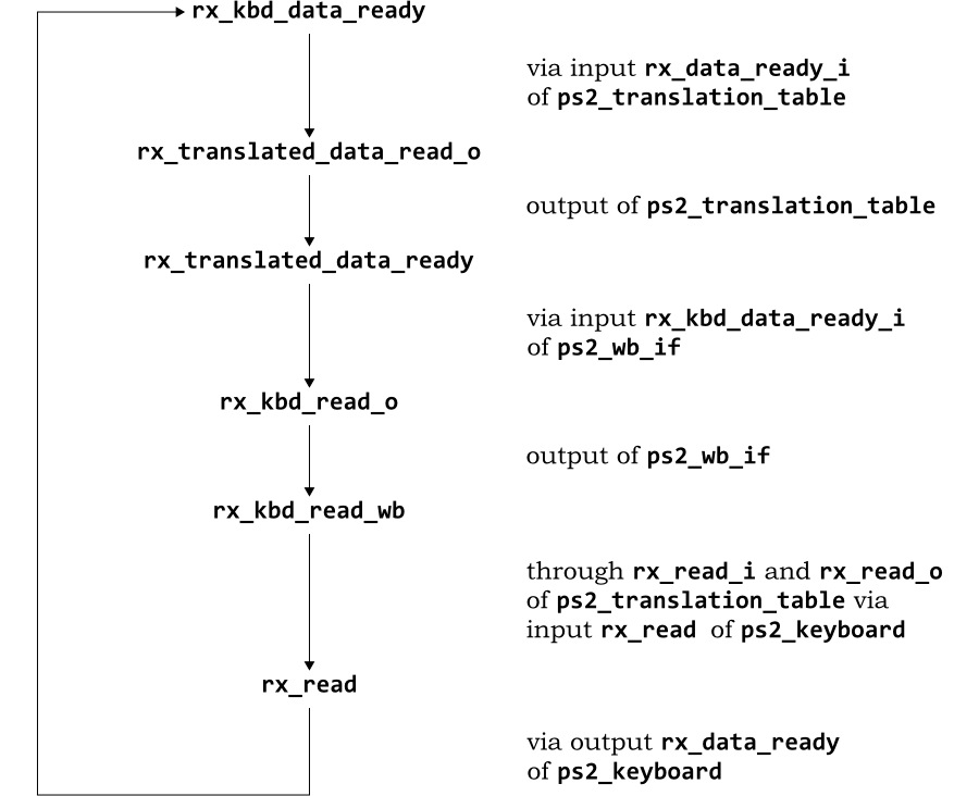
%Warning-UNOPTFLAT: ../local/rtl/verilog/ps2/ps2_top.v:154: Signal unoptimizable
: Feedback to clock or circular logic: v->ps2_top.rx_kbd_data_ready
%Warning-UNOPTFLAT: Use "/* verilator lint_off UNOPTFLAT */" and lint_on around
source to disable this message.
%Warning-UNOPTFLAT:      Example path: ../local/rtl/verilog/ps2/ps2_top.v:154:
v->ps2_top.rx_kbd_data_ready
%Warning-UNOPTFLAT:      Example path: ../local/rtl/verilog/ps2/ps2_translation_
table.v:310:  ASSIGNW
%Warning-UNOPTFLAT:      Example path: ../local/rtl/verilog/ps2/ps2_top.v:155:
v->ps2_top.rx_translated_data_ready
%Warning-UNOPTFLAT:      Example path: ../local/rtl/verilog/ps2/ps2_wb_if-2.v:68
4:  ASSIGNW
%Warning-UNOPTFLAT:      Example path: ../local/rtl/verilog/ps2/ps2_top.v:156:
v->ps2_top.rx_kbd_read_wb
%Warning-UNOPTFLAT:      Example path: ../local/rtl/verilog/ps2/ps2_keyboard-2.v
:429:  ALWAYS
%Warning-UNOPTFLAT:      Example path: ../local/rtl/verilog/ps2/ps2_top.v:154:
v->ps2_top.rx_kbd_data_ready
%Warning-UNOPTFLAT: ../local/rtl/verilog/or1200/or1200_sprs.v:212: Signal unopti
mizable: Feedback to clock or circular logic: v.or1200_top.or1200_cpu->or1200_sp
rs.read_spr

...
This is an important warning to address. It is identifying a set of signals which appear to have cyclic dependency—a combinatorial loop. Rather than evaluating the expression in a single step, Verilator will need to iterate until it settles.
Verilator identifies the problem signal, and at least one loop
through which it is being driven. In the first warning in the
example, the problem signal is rx_kbd_data_ready
at line 154 of ps2_top.v:
wire rx_released,
     rx_kbd_data_ready,
     rx_translated_data_ready,
...
The next line of the warning identifies that
rx_kbd_data_ready is driving
rx_translated_data_read_o at line 310 of
ps2_translation_table.v:
assign code_o = translate_i ? {(rx_released_i | ram_out[7]), ram_out[6:0]} : cod
e_i ;
assign rx_translated_data_ready_o = translate_i ? rx_translated_data_ready : rx_
data_ready_i ;
assign rx_read_o = rx_read_i ;
The connection is not immediately
obvious. rx_translated_data_ready_o is not
directly dependent on rx_kbd_data_ready. However
this is a different module, and Verilator has flattened the
code. The signal rx_data_ready_i is an input. In
the instantiation of ps2_translation_table in
ps2_top.v, the driving signal,
rx_kbd_data_ready is the argument used for the
rx_data_ready_i input:
ps2_translation_table i_ps2_translation_table
(
    ...

    .data_o                     (),
    .rx_data_ready_i            (rx_kbd_data_ready),
    .rx_translated_data_ready_o (rx_translated_data_ready),

    ...
) ;
The next line of warning identifies that
rx_translated_data_ready_o is driving
rx_translated_data_ready at line 155 of
ps2_top.v:
wire rx_released,
     rx_kbd_data_ready,
     rx_translated_data_ready,
     rx_kbd_read_wb,
     rx_kbd_read_tt,
Again the connection is not immediately clear, but the driving
signal (rx_translated_data_ready_o) is an output
of module ps2_translation_table. This is
connected to rx_translated_data_ready_o via its
instantiation in ps2_top.v:
ps2_translation_table i_ps2_translation_table
(
    ...

    .rx_data_ready_i            (rx_kbd_data_ready),
    .rx_translated_data_ready_o (rx_translated_data_ready),
    .rx_read_i                  (rx_kbd_read_wb),

    ...
) ;
The next line of warning identifies that
rx_translated_data_ready is driving
rx_kbd_read_o at line 684 of
ps2_wb_if-2.v (the previously modified version
of ps2_wb_if.v):
assign rx_kbd_read_o = rx_kbd_data_ready_i &&
                       ( enable1
                         ||
                         ( read_input_buffer_reg
                           &&
                           input_buffer_full
                           &&
                           !input_buffer_filled_from_command
                           `ifdef PS2_AUX
                           &&
                           !aux_input_buffer_full
                           `endif
                          )
                        );
Once again this is a different module, and the connection is through
an input to the module. In this case
rx_translated_data_ready is passed as input
rx_kbd_data_ready_i in the instantiation of
ps2_wb_if in ps2_top.v:
ps2_wb_if i_ps2_wb_if
(
    .wb_clk_i                      (wb_clk_i),
    .wb_rst_i                      (wb_rst_i),

    ...

    .rx_scancode_i                 (rx_translated_scan_code),
    .rx_kbd_data_ready_i           (rx_translated_data_ready),
    .rx_kbd_read_o                 (rx_kbd_read_wb),

    ...

) ;
The next line of warning identifies that
rx_kbd_read_o is driving
rx_kbd_read_wb at line 156 of
ps2_top.v:
wire rx_released,
     rx_kbd_data_ready,
     rx_translated_data_ready,
     rx_kbd_read_wb,
     rx_kbd_read_tt,
     tx_kbd_write,
     ...
Once again this is a different module, and the connection is through
an output of the module. In this case
rx_kbd_read_o is passed as output in the
instantiation of ps2_wb_if in
ps2_top.v, where it is connected to
rx_kbd_read_wb:
ps2_wb_if i_ps2_wb_if
(
    ...

    .rx_kbd_data_ready_i           (rx_translated_data_ready),
    .rx_kbd_read_o                 (rx_kbd_read_wb),
    .tx_kbd_data_o                 (tx_kbd_data),

    ...
) ;
The next line of warning identifies that
rx_kbd_read_wb in turn drives
rx_read at line 429 of
ps2_keyboard-2.v (an already modified version
of ps2_keyboard.v):
always @(m2_state or rx_output_strobe or rx_read)
begin : m2_state_logic
  case (m2_state)

    ...
The trail through the flattened modules is a little harder this
time. The driving signal, rx_kbd_read_wb is an
input (rx_read_i) to module
ps2_translation_table. Within that module it
directly drives (via a continuous assignment), the output
rx_read_o, which is connected to
rx_kbd_read_tt in ps2_top.v:
ps2_translation_table i_ps2_translation_table
(
    ...

    .rx_translated_data_ready_o (rx_translated_data_ready),
    .rx_read_i                  (rx_kbd_read_wb),
    .rx_read_o                  (rx_kbd_read_tt),
    .rx_released_i              (rx_released)
) ;
rx_kbd_read_tt is in turn the
rx_read input in the instantiation of
ps2_keyboard:
ps2_keyboard #(`PS2_TIMER_60USEC_VALUE_PP, `PS2_TIMER_60USEC_BITS_PP, `PS2_TIMER
_5USEC_VALUE_PP, `PS2_TIMER_5USEC_BITS_PP)
i_ps2_keyboard
(
    ...

    .rx_data_ready               (rx_kbd_data_ready),
    .rx_read                     (rx_kbd_read_tt),
    .tx_data                     (tx_kbd_data),

    ...
);
The final line of warning, identifies that
rx_read is in turn a driver of the original
signal, rx_kbd_data_ready at line 154 of
ps2_top.v, thus completing the loop.
The connection is through the rx_data_ready
output of ps2_keyboard instantiated in
ps2_top.v:
ps2_keyboard #(`PS2_TIMER_60USEC_VALUE_PP, `PS2_TIMER_60USEC_BITS_PP, `PS2_TIMER
_5USEC_VALUE_PP, `PS2_TIMER_5USEC_BITS_PP)
i_ps2_keyboard
(
    ...

    .rx_scan_code                (rx_scan_code),
    .rx_data_ready               (rx_kbd_data_ready),
    .rx_read                     (rx_kbd_read_tt),

    ...
);
The rx_data_ready output is driven from within
the always block dependent on
rx_read:
always @(m2_state or rx_output_strobe or rx_read)
begin : m2_state_logic
  case (m2_state)
    m2_rx_data_ready_ack:
          begin
            rx_data_ready = #1 1'b0;
            if (rx_output_strobe) m2_next_state = #1 m2_rx_data_ready;
            else m2_next_state = #1 m2_rx_data_ready_ack;
          end
    m2_rx_data_ready:
          begin
            rx_data_ready = #1 1'b1;
            if (rx_read) m2_next_state = #1 m2_rx_data_ready_ack;
            else m2_next_state = #1 m2_rx_data_ready;
          end
    default : m2_next_state = #1 m2_rx_data_ready_ack;
  endcase
end
The loop is summarized in Figure 7.1.
Combinatorial loops can be down to a number of causes. In many cases there is no loop at the bit level. The dependencies are on different bits in a multi-bit signal, none of which form a loop. Verilator looks for loops on the full register or wire, not the individual bits, so flags a warning. The solution in this case is easy - break the signal apart to its individual components.
But this is not the problem with this ORPSoC example. This is a
single bit signal, and a genuine combinatorial loop (which will
settle, so simulates correctly). The clue to fixing it is in the
combinatorial always block in
ps2_keyboard-2.v:
always @(m2_state or rx_output_strobe or rx_read)
begin : m2_state_logic
  case (m2_state)
    m2_rx_data_ready_ack:
          begin
            rx_data_ready = #1 1'b0;
            if (rx_output_strobe) m2_next_state = #1 m2_rx_data_ready;
            else m2_next_state = #1 m2_rx_data_ready_ack;
          end
    m2_rx_data_ready:
          begin
            rx_data_ready = #1 1'b1;
            if (rx_read) m2_next_state = #1 m2_rx_data_ready_ack;
            else m2_next_state = #1 m2_rx_data_ready;
          end
    default : m2_next_state = #1 m2_rx_data_ready_ack;
  endcase
end
There is no reason in a cycle accurate simulation (where
# delays are ignored) for
rx_data_ready to be set inside the
always block. Ignoring the delay, it is low
when m2_state == m2_rs_data_ready_ack and high
otherwise. The default entry is meaningless in
a 2-state simulation, since m2_state is a 1-bit
register.
The always block can be written with
rx_data_ready assigned outside the block, and
the loop is broken:
`ifdef verilator
assign rx_data_ready = ~(m2_state == m2_rx_data_ready_ack); // Breaks comb loop
`endif

always @(m2_state or rx_output_strobe or rx_read)
begin : m2_state_logic
  case (m2_state)
    m2_rx_data_ready_ack:
          begin
`ifndef verilator
            rx_data_ready = #1 1'b0;
`endif
            if (rx_output_strobe) m2_next_state = #1 m2_rx_data_ready;
            else m2_next_state = #1 m2_rx_data_ready_ack;
          end
    m2_rx_data_ready:
          begin
`ifndef verilator
            rx_data_ready = #1 1'b1;
`endif
            if (rx_read) m2_next_state = #1 m2_rx_data_ready_ack;
            else m2_next_state = #1 m2_rx_data_ready;
          end
    default : m2_next_state = #1 m2_rx_data_ready_ack;
  endcase
end
The remaining two loops both concern signals in
or1200_sprs.v. The command file
cf-optimized-7.scr has all these problems
fixed. A performance run need not now turn off any warnings.
make clean verilate COMMAND_FILE=cf-optimized-7.scr \
     VFLAGS="-language 1364-2001" NUM_RUNS=1000
This run gives a significant performance improvement over previous runs of 47.06 kHz.
This is one of two warnings that is really important to fix. The
other is UNOPT which occurs when modules have
input and output signals crossing between them, and which does not
occur in ORPSoC.
Even though there were only 3 loops, one of which was in a peripheral with tied-off inputs, fixing this problem gave an 8% performance improvement.
The final fix is to remove the constructs which conflict with SystemVerilog. This gives greatest flexibility in future development. These are errors, so will stop the compilation at the first error. The model build is run without restricting the language:
make verilate COMMAND_FILE=cf-optimized-7.scr
The first error is in eth_wishbone-3.v:
%Error: ../local/rtl/verilog/ethernet/eth_wishbone-3.v:579: syntax error, unexpe
cted do, expecting IDENTIFIER
%Error: Cannot continue
%Error: Command Failed /home/jeremy/tools/verilator/verilator-3.700/verilator_bi
n -Mdir . -sc -f v-processed.scr
This is the commonest trap set by SystemVerilog's new
keywords. do is often used in designs to
designate the data output. The problem is fixed by simple
substitution.
In this case the problem is the instantiation of
eth_spram_256x32.v in
eth_wishbone-3.v, which uses
do for its data output port. The solution is to
replace do with data_o. For
consistency, di is changed to
data_i at the same time.
This is the only such conflict in the ORPSoC source. A performance
run with the update command file
(cf-optimized-8.scr) yields no significant
change in performance at 47.5 kHz excluding Verilator model
build time.
Table 7.1 shows the performance gains which can be achieved by fixing the various Verilator warnings and language inconsistencies.
|
Run Description |
Build Time |
Run Time |
Performance |
|---|---|---|---|
|
Baseline |
13.94 s |
27.67 s |
42.66 kHz |
|
|
13.91 s |
27.59 s |
42.76 kHz |
|
|
13.91 s |
27.66 s |
42.66 kHz |
|
|
13.89 s |
27.77 s |
42.50 kHz |
|
|
13.92 s |
27.41 s |
43.04 kHz |
|
|
13.93 s |
27.24 s |
43.31 kHz |
|
|
13.92 s |
27.32 s |
43.20 kHz |
|
|
13.95 s |
25.07 s |
47.06 kHz |
|
SystemVerilog compliant |
13.91 s |
24.85 s |
47.49 kHz |
Table 7.1. Comparison of model performance when fixing Verilator warnings.
The table confirms that the majority of warnings do not greatly
affect performance. They are primarily about writing good quality
RTL. However fixing UNOPTFLAT gave a significant
performance improvement.
All the optimizations up to this stage have concerned getting the best possible model out of Verilator. There are now the optimizations to get from the C++ compiler.
All the performance figures in this section make use of the final
command file, cf-optimized-8.scr.
Verilator divides its code into two categories. That which is
executed every cycle ("fast" code) and that which is executed less
frequently ("slow" code). The OPT_FAST macro of
the Verilator generated Makefile specifies
optimizations to be applied to the "fast" code. Conversely the
OPT_SLOW macro specifies optimizations to be
applied to the "slow" code. For convenience the macro
OPT can be used to specify optimizations that
will be applied to both categories of code.
The separation allows focusing of optimization effort for large
designs, where compile times are significant. Just specifying
OPT_FAST gains most of the model performance
benefit, without the overhead of optimizing the "slow" code.
Table 7.2 shows the effect of using the GNU
C++ compiler's highest level of optimization
(-O3) with OPT_FAST,
OPT_SLOW and OPT. These can be
passed as macros to the Makefile in the example
for this application note:
make verilate COMMAND_FILE=cf-optimized-8.scr NUM_RUNS=1000 OPT_FAST="-O3"
|
Run Description |
Build Time |
Run Time |
Performance |
|---|---|---|---|
|
No optimization |
13.91 s |
24.85 s |
47.49 kHz |
|
|
33.78 s |
12.35 s |
95.51 kHz |
|
|
14.20 s |
25.35 s |
46.58 kHz |
|
|
35.35 s |
12.39 s |
95.25 kHz |
Table 7.2.
Comparison of model performance with different
Verilator OPT flag settings.
In the example used in this application note (which is not huge),
none of the model build times are unreasonable. As can be seen
OPT_SLOW profiling has no significant effect in
this example.
The GNU C++ compiler (like other Linux C++ compilers) offers various
levels of optimization from none (-O0) through to
(-O3). There is a trade off to be made—more
optimization means longer compile times, but faster run times.
GNU C++ also offers -Os, to optimize for
space. This is equivalent to -O2, but omitting any
optimizations that tend to increase the size of the program.
Table 7.3 shows the impact of the different optimization levels on the example design.
|
Run Description |
Build Time |
Run Time |
Performance |
|---|---|---|---|
|
|
13.98 s |
25.05 s |
47.10 kHz |
|
|
21.51 s |
13.13 s |
89.90 kHz |
|
|
32.77 s |
12.76 s |
92.46 kHz |
|
|
35.35 s |
12.39 s |
95.25 kHz |
|
|
26.23 s |
12.24 s |
96.41 kHz |
Table 7.3. Comparison of model performance with different compiler optimization settings.
Almost all the benefit is gained from -O1, but
there are incremental benefits, at the expense of greater compile
times for higher levels of optimization.
Note however that the highest performance is with
-Os. Code generated by Verilator (and its
commercial rivals) has a classic "cache-busting" structure. On each
code cycle execution starts at the top and proceeds linearly to the
bottom. Anything that reduces the code size, increases the
likelihood of code remaining in the cache, and so can have a very
large performance benefit.
The recommendation is to use -Os as the preferred
C++ compiler option.
Modern compilers, such as the GNU C++ compiler can optimize based on statistics from earlier runs of the compiled program. The program is compiled with options to gather statistics, run to create the statistics, then recompiled using the data from those statistics.
The latest versions of the GNU C++ compiler can use this for:
Reorganize branches to favor the most commonly taken branch
(option -fbranch-probabilities).
Optimize expressions based on knowledge of how they are used
(option -fvpt).
Unroll loops where this would be favorable in most cases
(option -funroll-loops).
Peel loops (i.e completely unroll and remove them), where they
would always be done a fixed number of times (option
-fpeel-loops).
Perform tail duplication where the resulting enlarged superblock
would improve other transformations (option
-ftracer).
Some care is needed in using branch-profiling. It can interact badly with other systems (for example ccache). Although it has been part of the GNU C++ Compiler for some years, it must still be regarded as somewhat experimental in nature.
Profiling is enabled with the example Makefile
by using the verilator-fast target. Statistics
are gathered by compiling the model with
-ftest-coverage and
-fprofile-generate options and then running it. The
options to be used in the subsequent optimizing recompile are passed
as a macro, PROF_OPTS, for example:
make verilate-fast COMMAND_FILE=cf-optimized-8.scr NUM_RUNS=1000 \
     OPT="-O3" PROF_OPTS="-fbranch-probabilities"
Table 7.4 shows the impact of the different
profiling options on the example design when compiled with
the -Os option, the fastest option without
profiling. The options are applied incrementally, in the order
-fbranch-probabilities, -fvpt,
-funroll-loops, -fpeel-loops and
-ftracer.
|
Run Description |
Build Time |
Run Time |
Performance |
|---|---|---|---|
|
No profile optimization |
26.23 s |
12.24 s |
96.41 kHz |
|
Add |
72.44 s |
11.94 s |
98.79 kHz |
|
Add |
73.88 s |
11.93 s |
98.93 kHz |
|
Add |
72.63 s |
12.00 s |
98.30 kHz |
|
Add |
72.65 s |
12.02 s |
98.17 kHz |
|
Add |
72.65 s |
11.99 s |
98.42 kHz |
Table 7.4.
Comparison of model performance using
-Os and profiling.
Model build times are all substantially bigger because of the need
to do a statistics gathering build and run. The results improve
slightly for the first two optimizations
(-fbranch-probabilities and
-fvpt), but then fall off. This is not
surprising. The benefit of -Os is compactness of
code size. However -funroll-loops,
-fpeel-loops and -ftracer all
tend to increase code size—reducing the caching benefit with
using -Os.
The added effort of profile directed compilation cannot be justified
when using -Os.
The same exercise is repeated, but this time to see the effect on a
compile using option -O3. The results are in Table 7.5.
|
Run Description |
Build Time |
Run Time |
Performance |
|---|---|---|---|
|
No profile optimization |
35.35 s |
12.39 s |
95.25 kHz |
|
Add |
83.51 s |
9.36 s |
126.10 kHz |
|
Add |
83.28 s |
9.34 s |
126.39 kHz |
|
Add |
83.78 s |
9.34 s |
126.39 kHz |
|
Add |
84.61 s |
9.27 s |
127.32 kHz |
|
Add |
85.87 s |
9.13 s |
129.28 kHz |
Table 7.5.
Comparison of model performance using
-O3 and profiling.
The results are dramatic. The
-fbranch-probabilities optimization gives the
majority of the benefit, but cumulatively the other four options
further increase performance. The results are significantly better
than using -Os.
The guideline advice is to use -O3 rather than
-Os if you have the opportunity to profile your
design.
The final stage is to look at the finished model for any modules which are dominating the compute time. These are candidates for replacement with equivalent modules optimized for cycle accurate modeling.
Common causes of performance bottlenecks are:
Built-in Self Test (BIST) code. Such code can be pervasive and bit-oriented, making it hard to model efficiently in a word-oriented environment like C++. BIST is not usually relevant to cycle accurate modeling. Substituting an equivalent model without BIST code can make a substantial performance improvement.
Behavioral memory models. Many memory models supplied by third parties are designed for behavioral accuracy during hardware verification. They will offer detailed and accurate intra-cycle performance modeling. Ports may well be buffered at the individual bit level.
Because memories are often so central to a design this can be a serious performance bottleneck. The solution is to replace them by a simple Verilog model which is concerned only with cycle accuracy and omits any buffering.
Associative (content-addressable) memories. These are efficient to implement in hardware, but a nightmare in software. In this case substitution in C/C++ using a hash-table is usually the best approach.
Bit-oriented code. Hardware handles bits as efficiently as words, but the same is not true of word-oriented C/C++. Such code can occur in many scenarios, but a common one is legacy designs for operations such as multiplication. Early synthesis tools did not make a good job of such operations, and so designs would be written out explicitly to make the functionality explicit.
Such designs can be huge, but are easily replaced by a single line of Verilog using the high level operation.
Verilator provides the -profile-cfuncs flag, which
adds additional information to the compiled code, identifying the
module to which it belongs. Compiling the model using the GNU C++
compiler's -g and -pg flags will
instrument the compiled code for profiling. A subsequent run will
generate a gmon.out file, which can be analyzed
using the standard gprof command.
Verilator provides a utility, verilator_profcfunc, for post-processing the results of the gprof. This breaks out the processing time by Verilog module name, rather than the underlying C++ function.
When profiling, no optimization should be used. Although the GNU C++ compiler allows optimized profiling, it can be a source of confusion, when parts of the code are optimized away. Unoptimized models are just as effective in highlighting any performance bottlenecks. With the example design, the following sequence of commands is appropriate:
make verilate COMMAND_FILE=cf-optimized-8.scr \
     VFLAGS="-profile-cfuncs" NUM_RUNS=1000 OPT="-g -pg"
gprof Vorpsoc_fpga_top > gprof.out
verilator_profcfunc gprof.out vprof.out
The first part of the output file, vprof.out
identifies where the execution time went:
Overall summary by type:
  % time  type
    4.62  C++
   17.45  Common code under Vorpsoc_fpga_top
   72.74  Verilog Blocks under Vorpsoc_fpga_top
    5.19  Unaccounted for/rounding error
The C++ code is code outside the Verilator model. In the example
used here, that is the SystemC test bench. The common code under
Vorpsoc_fpga_top is the common infrastructure
code. The Verilog blocks are the C++ code of directly derived from the
Verilog. Finally, there is time that was spent outside profiled
code. In this example, that will be largely due to the SystemC
kernel, but since gprof is based on statistical
sampling it also includes a small amount of time which cannot be
accounted for.
There is nothing significant in this example A warning sign to watch for is if the either the C++ or unaccounted figure is very high. That could be a problem with a SystemC test bench—perhaps with very wide ports.
The next section is a summary of the same information, grouping the common code and Verilog blocks:
Overall summary by design:
  % time  design
    4.62  C++
   90.19  Vorpsoc_fpga_top
    5.19  Unaccounted for/rounding error
In both these cases, instantiation of multiple models would make for more entries.
The third section is the most important. It shows how the execution time was broken down by originating Verilog module:
Overall summary by module:
  % time  module
    4.62  C++
   17.45  Vorpsoc_fpga_top common code
    0.11  dbg_crc8_d1
    0.00  dbg_register
    0.17  dbg_registers
    0.76  dbg_sync_clk1_clk2
    ...
This is provided in alphabetical order, but it is useful to cut out this section and sort it (using the command sort -n -r):
   17.45  Vorpsoc_fpga_top common code
    7.69  eth_wishbone_4
    5.17  or1200_du
    5.05  uart_regs_2
    4.62  C++
    3.77  tc_top
    3.41  eth_registers
    3.38  eth_crc
    3.07  dbg_top_3
The common code can be ignored—that is beyond control. Look for any small modules that are using a lot of processing.
| Note |
|---|---|
The names used are that of the originating file, not the module
name, with any hyphen ("-") mapped to underscore ("_"). Thus the
first example here is the module |
There are no real bit CPU hogs in this example. The largest user,
eth_wishbone-4.v uses over 7% of the execution
time, but it is a large block (more than 2,500 lines of Verilog), so
this is not unreasonable. The other modules at the top of the list are
also all big blocks of code.
It is worth observing that in the current model, the Ethernet is tied off and unused. If there is no intention to develop the model to use the Ethernet the instantiation could be removed altogether, perhaps improving performance by 20% or so. The same observation applies to a lesser extent with the other peripherals, currently unused.
The examples in this chapter can be distilled to some simple guidelines for obtaining the fastest possible models
Build new code so it does not generate Verilator warnings.
Most warnings can be ignored in known good legacy code. However
UNOPTFLAT (and UNOPT, which was not encountered here) should be
addressed, since they will lead to performance gains.
Use -O1 or -Os for simple C++
optimization, or where build time is onerous. For maximum speed
using -O3 with profiling.
Profile the generated model using gprof to identify any performance bottlenecks in the Verilog.
There is a trade off between increased time taken to create the model and reduced execution times of the resulting model. Key data points from the various optimization steps are summarized in Table 7.6.
|
Run Description |
Build Time |
Run Time |
Performance |
|---|---|---|---|
|
Baseline event driven simulation |
1.78 s |
796.84 s |
1.48 kHz |
|
Optimized event driven simulation |
1.78 s |
803.39 s |
1.47 kHz |
|
Baseline Verilator model |
13.94 s |
27.67 s |
42.66 kHz |
|
Verilator with all language fixes |
13.91 s |
24.85 s |
47.49 kHz |
|
Verilator |
26.23 s |
12.24 s |
96.41 kHz |
|
Verilator |
85.87 s |
9.13 s |
129.28 kHz |
Table 7.6. Summary of ORPSoC model performance with various optimizations.
These results are shown graphically in Figure 7.2.
This application note has shown how to build and optimize a cycle accurate model of a complete SoC in SystemC using Verilator. The steps can be summarized as:
Establish a baseline model using event driven simulation, against which subsequent Verilator models can be compared.
Build a baseline Verilator model starting from the same source hierarchy. Make RTL modifications where necessary to meet Verilator's language requirements, and disable warnings at this stage.
Show that any RTL changes still work correctly under event driven simulation.
Rerun Verilator with warnings enabled. In general fix all warnings
in new code, but only fix UNOPTFLAT and
UNOPT in working legacy code.
Show that any RTL changes still work correctly under event driven simulation.
Optimize the C++ compilation. Start using either
-O1 or -Os with the GNU C++
compiler.
If time permits use profile directed compilation of the C++ and
-O3.
Profile the finished model using gprof and Verilator's post-analysis utility. Consider disabling or optimizing any modules that are a serious performance bottleneck.
The starting point in this example was an event driven simulation of the SoC running at 1.4kHz. An initial Verilator model required a small number of changes to the RTL and achieved over 40kHz.
However, after following the steps in this tutorial, the final optimized model was capable of running at nearly 130kHz. These results are shown graphically in Figure 8.1.
The result is a cycle accurate SystemC model of a complete SoC, with a performance which makes low-level firmware development a quite feasible activity.
Suggestions for corrections or improvements are welcomed. Please contact
the author at jeremy.bennett@embecosm.com.
Hardware logic model which is based only on logic high and logic low (binary 0 and binary 1) values.
See also 4-state.
Hardware logic model which considers unknown (X)
and unproven (Z) values as well as logic high and
logic low (binary 0 and binary 1).
See also 2-state.
A description of the relationship between byte and word addressing on a computer architecture. In a big endian architecture, the least significant byte in a data word resides at the highest byte address (of the bytes in the word) in memory.
The alternative is little endian addressing.
See also little endian.
In an event driven simulator, the analysis of source Verilog to create an executable which will subsequently perform the simulation.
JTAG is the usual name used for the IEEE 1149.1 standard entitled Standard Test Access Port and Boundary-Scan Architecture for test access ports used for testing printed circuit boards and chips using boundary scan.
This standard allows external reading of state within the board or chip. It is thus a natural mechanism for debuggers to connect to embedded systems.
A linting compiler (or feature of a compiler) provides extra analysis of the source language to identify potentially dangerous constructs. The problems identified by such tools typically go beyond what the source language standard requires, to identify good practice in the use of the source language.
A description of the relationship between byte and word addressing on a computer architecture. In a little endian architecture, the least significant byte in a data word resides at the lowest byte address (of the bytes in the word) in memory.
The alternative is big endian addressing.
See also big endian.
The industry standardization body for SystemC
A silicon chip which includes one or more processor cores.
A set of libraries and macros, which extend the C++ programming language to facilitate modeling of hardware.
Standardized by the Open SystemC Initiative, who provide an open source reference implementation.
See also Open SystemC Initiative.
[1] Don Mills and Clifford E Cummings RTL Coding Styles That Yield Simulation and Synthesis Mismatches SNUG 1999 1999. www.sunburst-design.com/papers.
[2] Clifford E Cummings "full_case parallel_case", the Evil Twins of Verilog Synthesis. SNUG 1999 1999. www.sunburst-design.com/papers.
[3] Clifford E Cummings Nonblocking Assignments in Verilog Synthesis, Coding Styles That Kill! SNUG 2000 2000. www.sunburst-design.com/papers.
[4] Weicker, Reinhold. Dhrystone: A Synthetic Systems Programming Benchmark. Communications of the ACM, , 10, October 1984, 1013-1030.
[5] Doxygen: Source code documentation generator tool, Dimitri van Heesch, 2008 . www.doxygen.org
[6] Embecosm Application Note 2. The OpenCores OpenRISC 1000 Simulator and Tool Chain: Installation Guide. Issue 3. Embecosm Limited, November 2008.
[7] Embecosm Software Package 4. Cycle Accurate SystemC JTAG Interface: Reference Implementation. Embecosm Limited, January 2009. Available for free download from the Embecosm website at www.embecosm.com .
[8] GTKWave 3.1 Wave Analyzer User's Guide. February 2008. gtkwave.sourceforge.net/
[9] Icarus Verilog 0.9 Steve Williams, January 2009. www.icarus.com/eda/verilog
[10] IEEE Standard SystemC® Language: Reference Manual. IEEE Computer Society 2005 . IEEE Std 1666™-2005. Available for free download from standards.ieee.org/getieee/1666/index.html .
[11] The OpenRISC Reference Platform System-on-Chip Available for download from www.opencores.org
[12] SystemC Version 2.0 User Guide. Open SystemC Initiative, 2002. Available for download from www.systemc.org
[13] Verilator 3.700. Wilson Snyder, January 2009. www.veripool.org/wiki/verilator