| Services - tools - models - for embedded software development |
|---|
| Services - tools - models - for embedded software development |
|---|

 |  | |
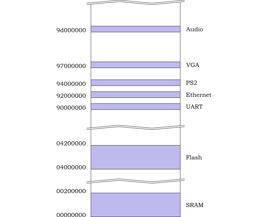
The memory map used is shown in Figure 3.1. This is slightly different from the memory map described in the ORPSoC documentation. However these are the values used in the standard distribution, which is a known working configuration.
During reboot, instruction fetches have 0x0400000 added. This means that the reboot sequence (which starts at 0x100) will fetch code from the Flash memory (0x04000100). This allows initial boot up code to be copied down into RAM.
| |  | |
| Chapter 3. The Example Design |  | 3.2. Interrupt Assignment |