 | Services and Modeling for Embedded Software Development |
|---|
| Services and Modeling for Embedded Software Development |
|---|

 |  | |
Or1ksimIntrSC Module Class
All the models in previous chapters have considered only the main WishBone bus interface to the OpenRISC 1000. However the processor also provides a debug interface, which at the hardware level is implemented via a IEEE 1149.1 JTAG.
At the simplest level, it is easy to have a transactional view of JTAG. Registers are shifted in and registers are shifted out. A simple read-modify-write transaction.
The difficulty is that JTAG is a bit serial interface, whereas TLM 2.0 really models simple reads and writes over bus interfaces (such as WishBone). The solution is to represent the JTAG register in a byte vector, and use a TLM 2.0 generic payload extension to describe the JTAG specific characteristics of bit length and target action (reset, shift through the instruction register or shift through the data register). This is described in Section 11.2.
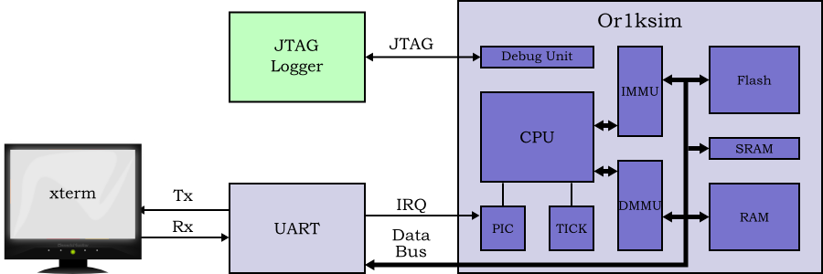
The example design extended to support JTAG was shown in Section 3.1.4, but for convenience the diagram is repeated here in Figure 11.1.
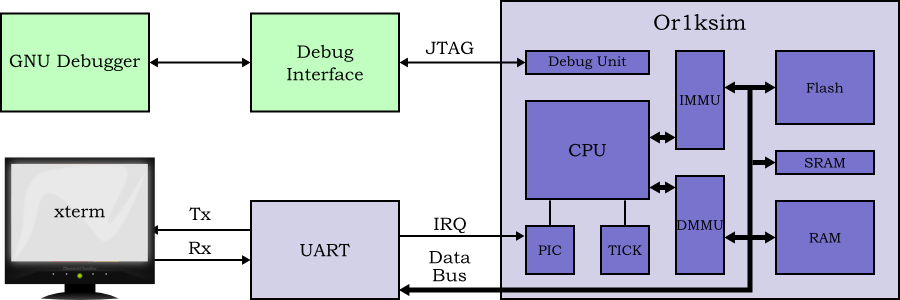 |
Figure 11.1. Simple SoC based on the OpenRISC 1000 Or1ksim with interrupts, MMU and JTAG debug interface.
For this example, a full debugger is not used to drive the JTAG
interface. Instead a simple JTAG logger,
JtagLoggerSC, is used. This initializes the
JTAG interface, then reads the Next Program
Counter (NPC) SPR once per second. This
is achieved by shifting a JTAG register for a debug unit
WRITE_COMMAND to specify the SPR to read, followed
by shifting a JTAG register for a debug unit
GO_COMMAND to read the actual register. This
simplified design is shown in Figure 11.2.
The Or1ksimIntrSC is extended with a new TLM 2.0
target port and handler for JTAG. This in turn requires a new TLM 2.0
generic payload extension class, JtagExtensionSC.
The code for the Or1ksim wrapper with JTAG interface
(Or1ksimJtagSC.cpp,
Or1ksimJtagSC.h), the code for the generic payload
extension (JtagExtensionSC.cpp,
JtagExtensionSC.h), the code for the JTAG logger
(JtagLoggerSC.cpp,
JtagLoggerSC.h) and the main program for the
complete model (jtagSocMain.cpp) may be found in
the sysc-models/jtoc-soc directory of the
distribution.
| | | |
| 10.5.2. Running Linux |  | 11.1. Overall Design of the SoC Model with JTAG Interface |