Back when the concept of an ‘electronic brain’ was new, the methods for storing information necessary for the running of the computer were primitive. Many early computers used punched paper tape, and EDSAC was no different. EDSAC used five hole wide punched tape which was fed through a tape reader so that it could be read by the computer.
Our Tape Reader
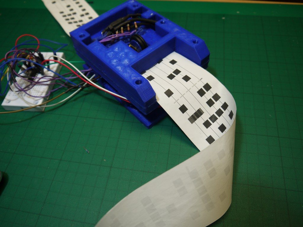
In our quest to reimagine EDSAC with the spirit of the original, we decided to build a tape reader to read tape in a similar manner. Our tape reader does however have some significant differences. Most notable of these is that our tape doesn’t actually have any holes in it. Instead, we reflect light off paper with dots printed on it towards light dependent resistors to detect them. We printed this tape using a thermal printer — similar to those found in tills to print receipts — to an Arduino. This allows us to print tape up to 12 meters long, although we haven’t needed that much yet!
The Design

We used a 3D printed frame to hold our components, with a slot through the middle into which we could feed our tape. A micro gear motor was used to pull tape through the reader. In the layer above our slot we held both the row of LEDs to illuminate the paper, and our row LDRs and carbon resistors to detect the markings on the paper tape. We put each LDR in series with a 22kΩ resistor and attached a wire in between to connect to the chip analogue inputs. The LDR and resistor act as a potential divider, giving us a varying voltage delivered to the input as the darkness of the paper markings changed the resistance of the LDR. We discovered that the resistance of the LDR averaged around 18kΩ between light and dark, and chose a roughly similar resistance with the 22kΩ to create the most distinct variance in the analogue input as the LDR resistance varied.
Coding
Since both the quality of my soldering and ambient light levels caused significant variance in the values read by each of the five analog inputs, a program designed to detect the dots on the tape by absolute value of the analogue inputs alone would be impossible, due to the continuous need to recalibrate for passing clouds, which would quickly become tiresome and time consuming. As such, a program was devised to detect the change over a short period of time of the values which the analogue inputs were recording. By using multiple overlapping periods we could detect periods of significant change, whilst ignoring natural random variance. This system still needed calibrating, but was far less sensitive to environmental changes.
Testing
There are a couple of significant values we can change in our code to make the reading more accurate. The first of these is the length of a measuring period, and another is the threshold for how much of a change during that period is required for the period to be considered significant. The measuring period is measured in milliseconds, whereas the threshold is based on the number given to us by the analogue input. This ranges between 0 and 1023, but the difference between a dot and not-a-dot is usually about 50. The testing isn’t finished yet; the reader still needs significant adjustment before it can accurately and effectively read the tape.
The Arduino code and SCAD files for the 3D printed parts can be found on GitHub: