Here at Embecosm HQ we’ve been busy finalising the design for all of our peripherals for the FPGA implementation, and re-imagining of the original EDSAC ready for Chip Hack. In this blog post, we’ll take you through what we’ve been doing, and how you too can build some peripherals of your own.
There are four peripherals we’re trying to recreate. I’ve been working on are a teleprinter, a front panel for loading the initial orders, and the paper tape reader (see also my previous post about this peripheral). My colleague, Mary Bennett, has been working on an air delay line as a substitute for a mercury delay line. All the designs can be found in the edsac-peripherals Github repository.
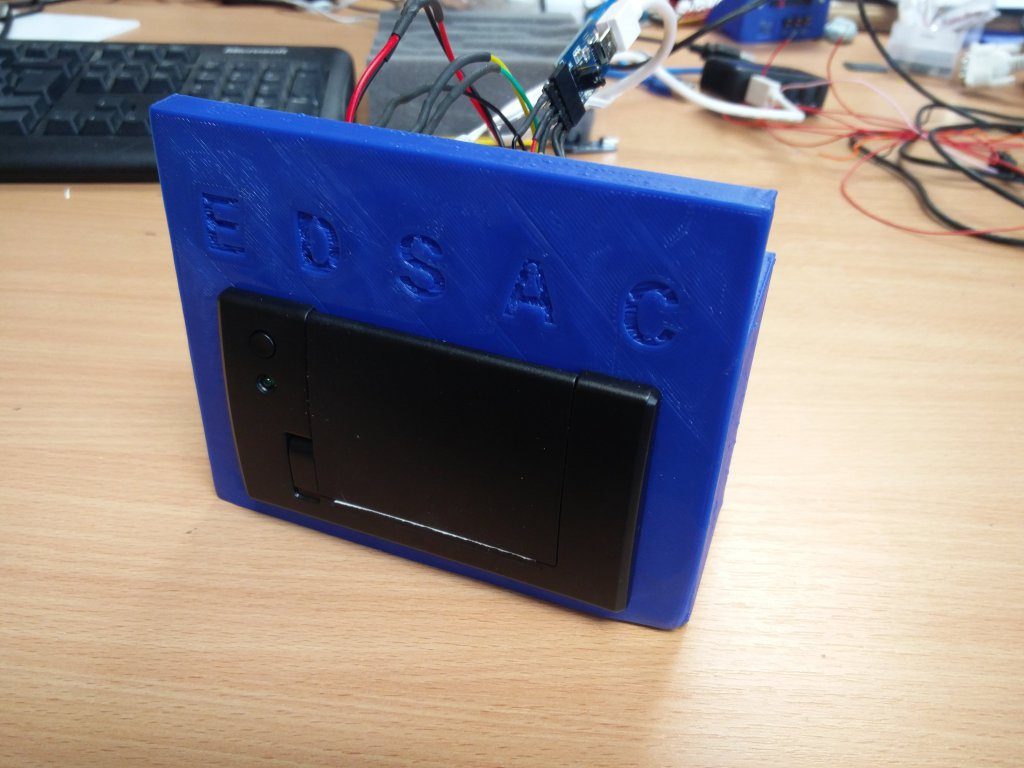
The teleprinter
The teleprinter is now physically complete, including a 3D printed case and microcontroller to drive it. We’ve uploaded a full bill of materials and designs for the 3D printed components to our GitHub repository. We are still working on the full build instructions, but in the meantime Adafruit have a great tutorial on using these tiny printers and we’ve put up some images with this post too, to give you an idea of how we put ours together. The teleprinter serves two purposes: firstly to provide an output for code written for the FPGA EDSAC implementation, and secondly to create the paper tape to be read by the tape reader. In terms of code, we’re not fully there yet on both fronts, but the code is in the GitHub repository and I encourage you to explore it.
The front panel

The original EDSAC used rotary uniselectors to input the initial instructions (known as orders) for booting the computer. Rather than try to rebuild a rotary selector, we have chosen to use a double row of header pins and jumpers.
With easily the most wiring of all the peripherals, this one looks like a right cat’s cradle in the pictures. Orders are loaded by creating a connection between a pin on the top and bottom rows, or by leaving them disconnected, creating a 17-bit string of zeroes and ones. Since there were up to 40 initial orders on the original EDSAC, we’re adding some 7-segment displays to help keep count of what orders you’ve loaded. There are also three buttons and status LEDs, although the exact functions of these haven’t been finalised. One function will be to send the selected order to EDSAC. The full bill of materials and the 3D designs are available on GitHub. Instructions and the circuit diagram will follow in due course, but in the meantime the photos above give an indication of how it is put together. The code is still a work in progress, but you can view its current state via the repository.
The tape reader
I’ve talked about this in my previous post, and there hasn’t been as much change here as with the other peripherals. However, there have still been some significant changes. The biggest of these is the addition of a sixth row as a clock line, which serves to allow more reliable reading of orders without requiring perfectly even rate of pull by the motor. We’ve also added a grub screw to hold the motor in place and another grub screw on the drive wheel to hold that more firmly on the shaft. As with the other peripherals, the code isn’t complete yet, but can be viewed on the repository. A bill of materials is now available too.
The air delay line
My colleague, Mary Bennett, has been working on an air delay line to represent the mercury delay lines used as memory for the original EDSAC. There will be a full post on this coming soon, so watch this space. Here are some pictures just to show you how this is progressing.