Introduction
So, I’m Mitchell Granger and this winter I had the pleasure of completing my second fortnight of work experience at Embecosm. You may remember if you read the blog, that on my previous visit here I was tasked with creating a timer for the clock pendulum at St. Thomas’ church next door. Since then, I have gone away and started a BTEC at Brockenhurst College. For this I had to complete a second fortnight of work experience, hence the reason for my second visit.
The Task
This time I was tasked with creating a crystal radio set based on the descriptions and schematics in ‘[A Ladybird Book] Making a Transistor Radio’. Problems arose in that this book was published decades ago and many of the components are obsolete, ergo, the task involved more than just creating a crystal radio set. I had to source replacement components – a task that began long before the start of my two week placement – and I was also tasked with writing up some corrections for the book so that it can be used in modern times. Unfortunately, due to unforeseen complications, I was unable to get this far in just two weeks.
This time the task involved no programming/coding, so my lack of knowledge in that department wasn’t an issue. However, it did require a lot in the way of electronics. Fortunately, this is an area of my knowledge that has been improved and widened over the last two years. Nevertheless, the project was challenging and definitely showed gaps in my knowledge.
Components
The first task that needed completing was the act of sourcing new components and creating a component list. This was a task that I began months before my two weeks started in January 2019. So much so that I had a components list completed by late November 2018. The reason for completing the task before I began was so that the necessary parts and components could be ordered in time for me to begin working on the circuits as soon as I started. Some of these components were the same as the ones in the book, such as the crystal earpiece, whereas modern replacements had to be sourced for others, such as the 500pF variable capacitor . [I feel inclined to point out that I later discovered that 500pF variable capacitors can still be found on eBay, but they are listed infrequently and aren’t always available]. Finally, due to the different characteristics of some of the replacement components, other components such as resistors and capacitors had to be experimented with to find the ideal values.
Beginning

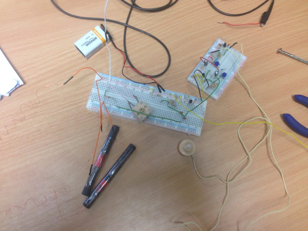
The first thing I had to do when I started my two weeks was to create the basic tuning circuit. The main part of this task was to create a ferrite coil inductor. To match this up with the new value of variable capacitor, I used an equation that I got from one of my teachers at college :- original number of turns(original capacitance/new capacitance) = 50(500×10-12/266×10-12).
To complete this stage I had to solder some short wires to the necessary legs of the variable capacitor and coil so that they could be connected to the breadboard. By the end of my first day I had built stages one to three of the book (tuning circuit to biased transistor amplifier). However, without an input from a signal generator or an antenna I couldn’t test this circuit.
Testing and Adapting
At this point I had an antenna that provided an input into the circuit. However, this antenna was only around a foot in length, (an inadequately short length as I later discovered) and I wasn’t getting any form of noise output from the earpiece. Preferring a more reliable input I set about researching possible alternative inputs such as circuits that produced a rough sine wave.
Meanwhile, Lewis – who was managing and helping me – was creating a circuit on an Arduino which would produce a rough sine wave. A few hours later I was using an Arduino generated sine wave as my input. However, this wasn’t giving any form of output either – I assumed because the low frequency (160Hz) was being tuned out by the tuning circuit and we soon returned to the antenna. This time about two or three feet in length. This still wasn’t producing an audible noise and after running an oscilloscope over the amplifier I discovered that the amplifier wasn’t amplifying at all. This proved to be the beginning of a task that lasted well over a week, namely, producing a working transistor amplifier. Over the course of the following days I tried various new amplifiers using both the original PNP BC557B transistor as well as the BC457 and BC457B NPN transistors but all to no avail.

By the end of my first week my attention had moved back onto the input – I had now abandoned the amplifier altogether. During my research I discovered a circuit that could turn a square wave input into a sine wave output. So while Lewis converted the sine wave generator program to a square wave generator program I set about creating this square wave converter. Before long, and after some alterations such as capacitor and resistor values as well as the number of capacitors and resistors, we had a circuit which produced a sine wave, albeit an imperfect one. This was at a much greater frequency of 160KHz but was still out of range for the tuning circuit. So by the end of the first week we were still going around in circles trying to obtain an adequate signal.

Week Two
The first task at the start of this week was to erect a longer antenna. This stretched from my desk to the window – around 5 metres – when complete. I found out, after appealing to an online forum, that this should be capable of picking up a signal from our nearest transmitter in Fareham 27Km away. However, the signal would be weak, and the output sound quiet. I also wound a second coil, after a recommendation from the same forum, that had less turns or loops and therefore, had a lower range of tuned frequencies. However, I believe this range was towards the lower bracket of the medium wave (MW) frequencies (below 900KHz) – though I can’t be sure – and therefore couldn’t pick up any of the locally transmitted frequencies which were all above 900KHz. Ergo, I created a third coil with slightly more loops which was capable, in theory, of tuning these slightly higher frequencies.
Before I could go any further it became necessary to move and extend the antenna. There were two reasons for this: a) the antenna currently ran across

two desks and was completely in the way, and b) it was also a rather obvious and unsafe trip hazard. To fix these issues I ran a new, longer antenna, consisting of the old antenna soldered to new lengths of wire, on the ceiling over to the same spot by the window. This had the positive effect of extending the antenna, however, I was still getting no audible output. At this point I had a transistor amplifier – though I don’t think it was amplifying – that I was connecting up to the circuit every now and then just for a change and to try new things.
Up until now the circuits ground had been the ground pin on the Arduino board. However, it was pointed out to me that this was an electrical ground and was therefore, not suitable for a crystal radio circuit which had to be a physical ground or earth. In a feeble attempt to achieve this without running a cable out of the office and down the stairs, I connected a long cable to the ground of the circuit and chucked it on the floor – another idea from the forum. At this point I also ran the end of the antenna (about three feet of it) out of the window in an attempt to obtain a better reception or even just a reception.
By the middle of the week I was beginning to suspect that the diode wasn’t suitable after reading an article about this subject online. However, I had to continue with this for the time being. At this point I still had no audible output, but I did have an operating transistor amplifier with a gain of about 27 times. This amplifier was similar to the one in the book and still used a PNP transistor, however, it was based on an amplifier that Lewis found and which had more resistors of different values as calculated by Lewis.
The next step was to add a second transistor. This one used the same configuration as the first one designed by Lewis, however, it was actually a blend of that one and the second transistor in the book. The resistor values were the same as those for the first amplifier and they were also in the same place relative to the transistor, however, it incorporated a potentiometer and an electrolytic capacitor of 10uF just like the second amplifier described in the book. With two transistors I was getting a much greater gain of approximately 157 times. With this new amplifier configuration I was finally getting some crackling out of the earpiece, but I couldn’t get a recognisable sound such as someone talking.

Finally, I added a third transistor, identical to the second one which further increased the gain and made the sound coming out of the earpiece even louder. It was at this point that I discovered that putting a 10K resistor in parallel with the potentiometer improved the volume,. Yet, without a tuned frequency I couldn’t be sure that it would improve the tuned output sound at all.
On the final day I was able to get hold of some alternative diodes that I’d been told should be better than the 1N60P that I had been using. I removed the 1N60P and tried each of these different types of diode in turn. Some made absolutely no difference at all, whilst others made a huge difference. Using a 1N3470 I was able to get some recognizable words out of the earpiece from a tuned station. However, these were very faint and there was still a lot of crackling which made it even harder to hear. Fortunately though, I could be sure they were definitely words which means that the circuit does work. I managed to recognise a couple of words, such as Chelsea and Fellaini; this made me suspect that I was tuned to either BBC Radio 5Live at 909KHz or TalkSPORT at 1107KHz. Unfortunately, the tuned signal was unreliable and I kept losing reception, but at least it worked.
The last thing I tried before I left the office for the final time was putting two coils in parallel. I connected a smaller coil between the antenna and ground whilst the other longer coil was left in parallel with the variable capacitor and the amplifiers, the input into the circuit being provided by a magnetic connection between the two coils. The thinking behind this adaptation is that it is supposed to get rid of some of the background noise which makes the radio signal more difficult to hear. Whilst this did appear to happen I also lost the audio output I was getting. However, even when I put the circuit back to how it was originally I couldn’t find the radio frequency either.
Another improvement that would have to be made to further this particular radio is to create some form of insulated spindle because I had to adjust the variable capacitor with a pair of metal pliers and this was having an adverse effect on the output and, possibly, on the tuned frequency itself. However, the two main things that would need to be significantly improved in order to make this work is the antenna and the ground. The antenna needs to be longer, outside and further away from the mains and computers, whilst the ground needs a better connection to ground either through a conductive stake driven into the ground or a connection to the buildings plumbing.
In Summary

Though the work was enjoyable, it was also challenging and there were many tedious points such as trying to find a successful amplifier. The sense of excitement and relief when I finally heard a recognizable word through the earpiece was unbelievable. I also believe that what I have learnt and achieved will help me moving forward at University and even later in life.